Isuzu KB P190. Manual — part 349
6A-36 ENGINE MECHANICAL (4JK1/4JJ1)
Inspection
• Inspection of the exhaust manifold. Inspect the
plane surface of the plane on which the
manifold and the cylinder head are to be
installed.
Manifold installation plane surface
mm (in)
Standard
0.3 (0.01) or lower
Limit 0.5
(0.02)
Note:
If the plane surface exceeds the limit, replace it.
LNW21BSH022301
• Check a crack in the exhaust manifold visually.
Carefully inspect the turbocharger for abrasion and/or
excessive wear. Make any necessary adjustments,
repairs, and/or part replacements.
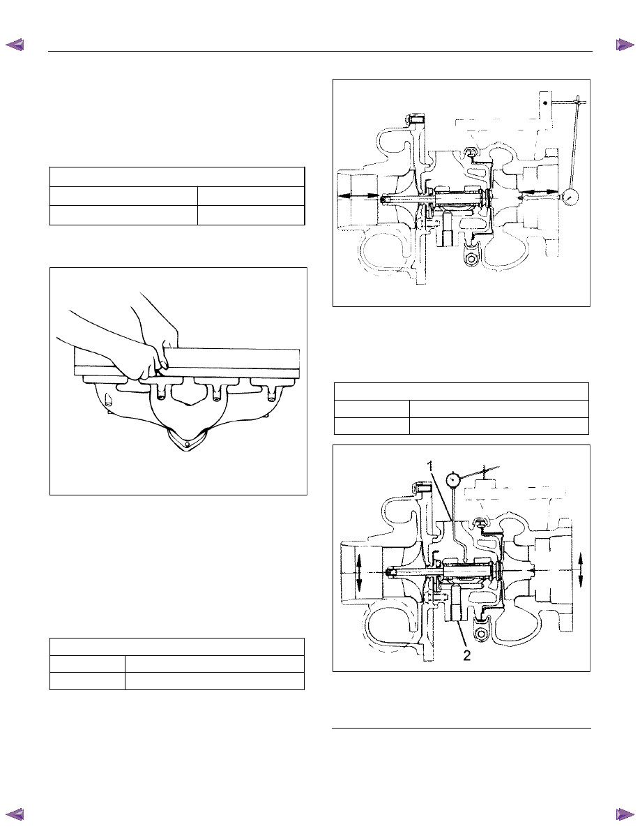
Wheel shaft axial play
Use a dial gauge to measure the wheel axle shaft play
when a force of 12 N (1.2 kg / 2.6 lb) is alternately
applied to both sides of the compressor wheel.
Axial play
mm (in)
Standard 0.03
− 0.06 (0.0012 − 0.0024)
Limit 0.09
(0.0035)
LNW21BSH022201
Wheel shaft and bearing clearance
Use a dial gauge to measure the clearance between the
wheel shaft and the bearing.
Clearance mm
(in)
Standard 0.056
− 0.127 (0.0022 − 0.0050)
Limit 0.14
(0.0055)
LNW21BSH022301
Legend
1. Oil Outlet
2. Oil Intake
ENGINE MECHANICAL (4JK1/4JJ1) 6A-37
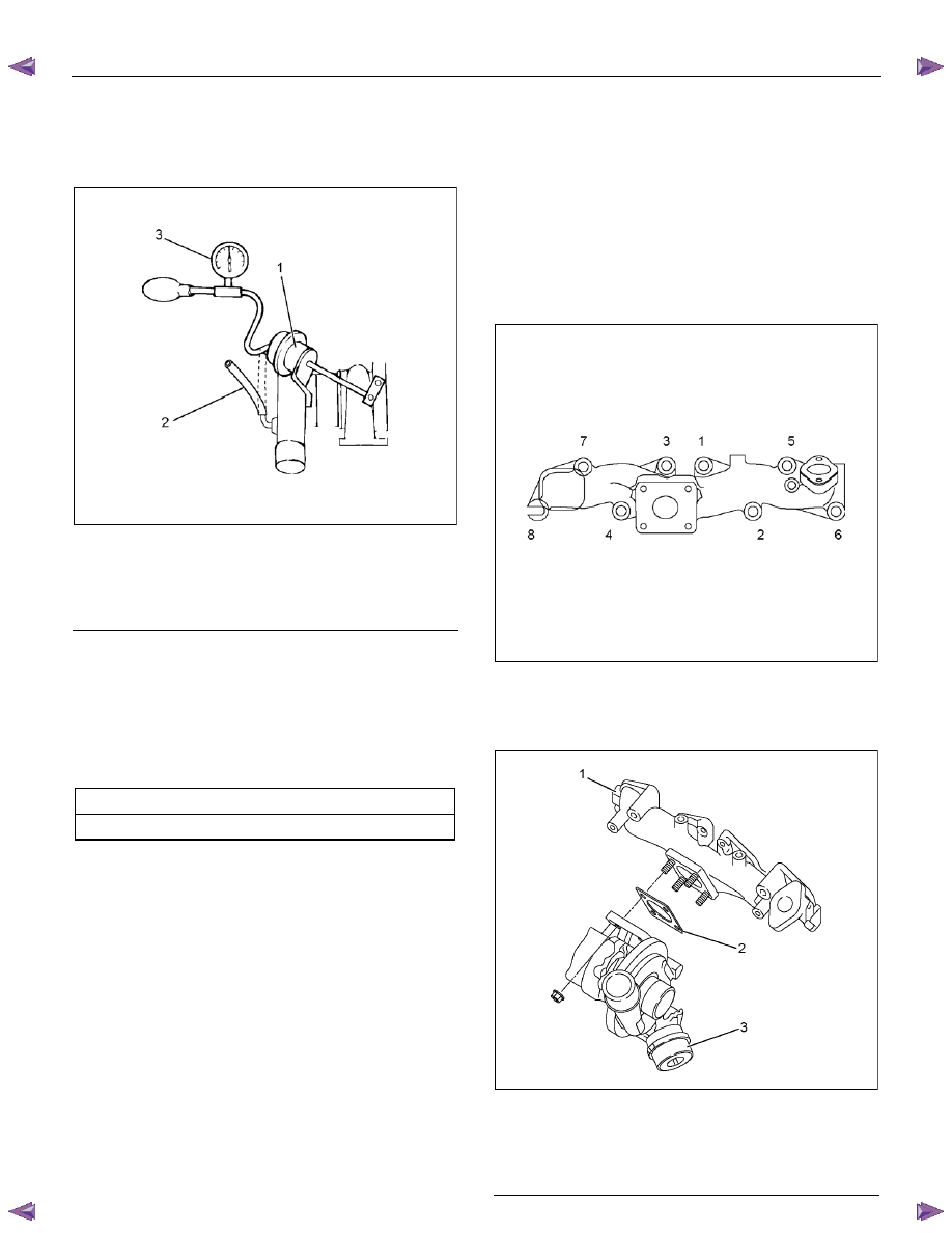
Waste gate operation
1. Remove the hose from the waste gate actuator.
2. Install the pressure gauge (general tool). Refer to
the illustration.
RTW56ASH005701
Legend
1. Waste Gate Actuator
2. Waste Gate Hose
3. Pressure Gauge (General Tool)
3. Use the pressure gauge pump to apply pressure
(load) to the waste gate actuator (the engine must
be off).
4. Note the pressure at which the control rod moves
2 mm (0.078 in). This pressure must be within the
specified limit.
Control rod pressure range:
kPa (mmHg / psi)
109
− 118 (818 − 885 / 16 − 17)
5. Inspect the hose for cracks and other damage.
Replace the hose if necessary.
6. Do not apply a pressure of more than 120 kPa
(900 mmHg) to the waste gate actuator.
Installation
1. Put the gasket in to install the exhaust manifold.
• Tighten up with the 8 nuts according to the
order given in the figure.
Tightening torque: 52 N
⋅⋅⋅⋅m (5.3 kg⋅⋅⋅⋅m / 38 lb ft)
Note:
Do not tighten up too much because it hampers
expansion and contraction due to the heat from the
manifold.
RTW56ASH005801
2. Install the gasket and turbocharger to the exhaust
manifold. Tighten the nuts to the specified torque.
Tightening torque: 27 N
⋅⋅⋅⋅m (2.8 kg⋅⋅⋅⋅m / 20 lb ft)
RTW56ASH005501
Legend
1. Exhaust
Manifold
2. Gasket
3. Turbocharger
6A-38 ENGINE MECHANICAL (4JK1/4JJ1)
3. Install the catalyst converter.
Tighten the nuts to the specified torque.
Tightening torque: 27 N
⋅⋅⋅⋅m (2.8 kg⋅⋅⋅⋅m / 20 lb ft)
4. Connect the front propeller shaft flange (Front Diff
Side, 4
×4 only).
5. Install the front exhaust pipe.
Tighten the nuts to the specified torque.
Tightening torque
Exhaust Manifold Side: 67 N
⋅⋅⋅⋅m (6.8 kg⋅⋅⋅⋅m / 49 lb ft)
Exhaust Pipe Side: 43 N
⋅⋅⋅⋅m (4.4 kg⋅⋅⋅⋅m / 32lb ft)
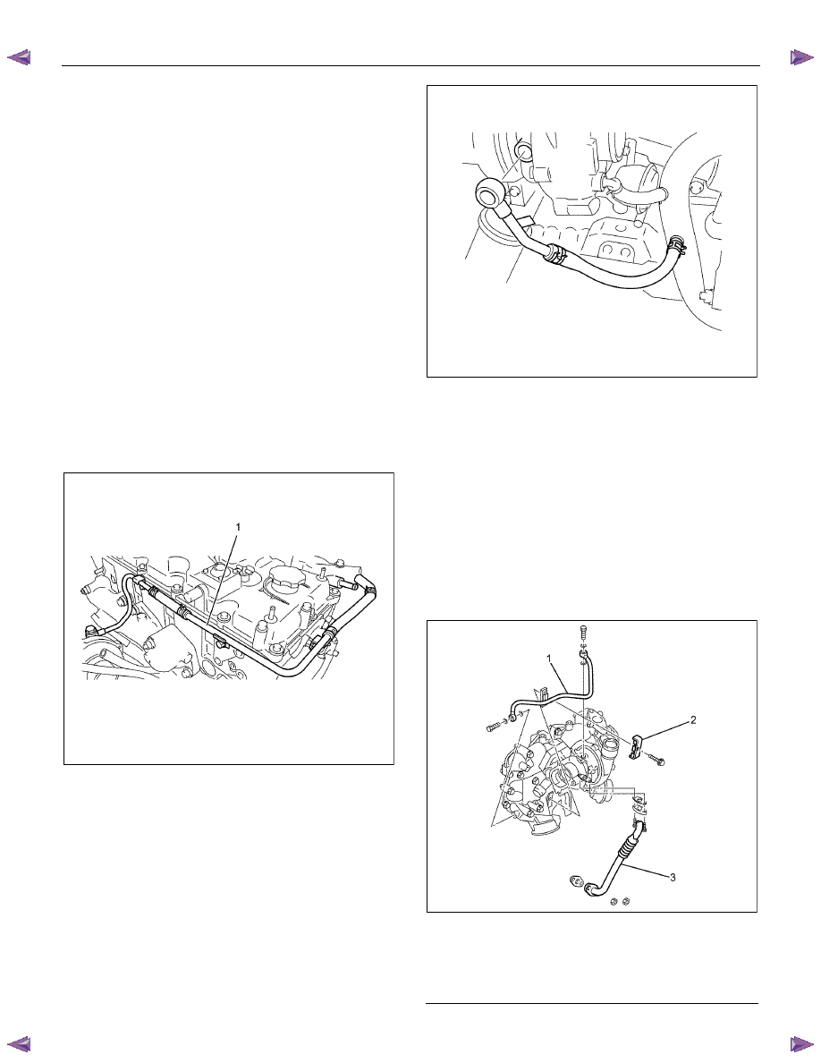
6. Install the water feed pipe to the turbocharger (1).
• Tighten the joint bolts to the specified torque.
Tightening torque: 54 N
⋅⋅⋅⋅m (5.5 kg⋅⋅⋅⋅m / 40 lb ft)
• Install the pipe bracket and tighten the bolts to
the specified torque.
Tightening torque: 10 N
⋅⋅⋅⋅m (1.0 kg⋅⋅⋅⋅m / 87 lb in)
• Install the rubber hose between the water
return pipe and the thermostat housing.
RTW56ASH019101
7. Install the water return pipe. Tighten the joint bolt
to the specified torque.
Tightening torque: 54 N
⋅⋅⋅⋅m (5.5 kg⋅⋅⋅⋅m / 40 lb ft)
RTW56ASH019001
8. Install the turbocharger oil feed pipe to the top of
the turbocharger. Tighten the joint bolts to the
specified torque.
Tightening torque (Turbo charger side):
23 N
⋅⋅⋅⋅m (2.3 kg⋅⋅⋅⋅m / 17 lb ft)
Tightening torque (Oil cooler side):
23 N
⋅⋅⋅⋅m (2.3 kg⋅⋅⋅⋅m / 17 lb ft)
• Install the pipe bracket and tighten the bolts to
the specified torque.
Tightening torque: (Clip)
10 N
⋅⋅⋅⋅m (1.0 kg⋅⋅⋅⋅m / 87 lb in)
RTW56ASH00610
Legend
1. Oil Feed Pipe
2. Clip
3. Oil Return Pipe
ENGINE MECHANICAL (4JK1/4JJ1) 6A-39
9. Tighten the oil return pipe bolts and nuts to the
specified torque.
Tightening torque (Turbocharger side):
10 N
⋅⋅⋅⋅m (1.0 kg⋅⋅⋅⋅m / 87 lb in)
Tightening torque (Crank case side):
25 N
⋅⋅⋅⋅m (2.5 kg⋅⋅⋅⋅m / 18 lb ft)
10.Install the EGR cooler.
• Refer to “EGR Cooler” in EXHAUST SYSTEM
section.
11. Install the heat protector.
• Refer to “EGR Cooler” in EXHAUST SYSTEM
section.
12. Install the intake hose between the intercooler and
the intake throttle (7).
13. Install the intake hose between the turbocharger
and the intercooler (9).
14.
Install the intake duct between the turbocharger
and the air cleaner (8).
Tightening torque: 6 N
⋅⋅⋅⋅m (0.6 kg⋅⋅⋅⋅m / 52 lb in)
15.Replenish the coolant.
Нет комментариевНе стесняйтесь поделиться с нами вашим ценным мнением.
Текст