Isuzu KB P190. Manual — part 511
6A-30 ENGINE MECHANICAL (C24SE)
Toothed Belt Rear Cover
(Engine with toothed belt tension
roller)
Removal
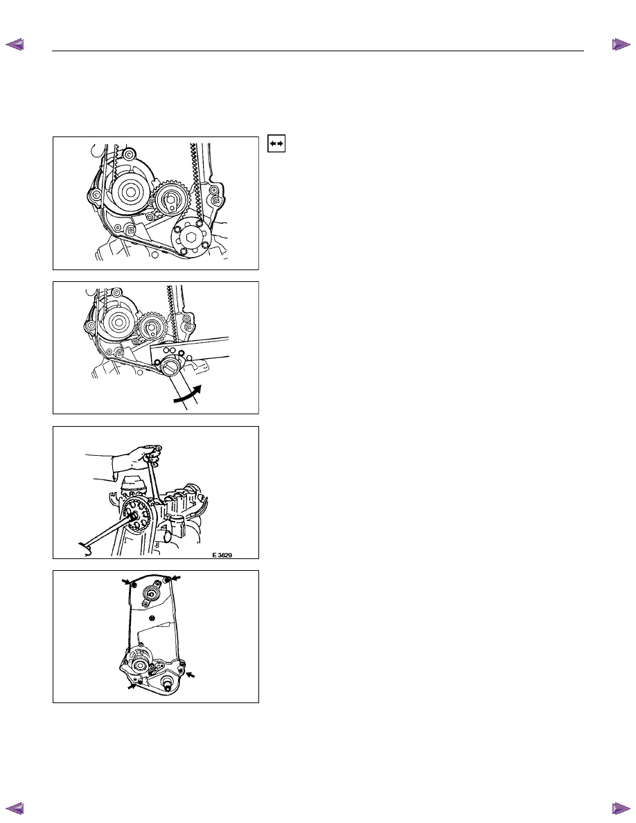
1. Mark operating direction of toothed belt.
2. Remove toothed belt according to the operation "Toothed
Belt".
3. Remove toothed belt tension roller according to the
operation "Toothed Belt Tension Roller ".
4. Remove fastening bolt while counterholding with 5-8840-
2598-0 (Holding wrench).
5. Remove toothed belt drive gear while counterholding with
5-8840-2598-0 (Holding wrench).
6. Remove camshaft housing cover.
7. Remove camshaft pulley while counterholding at hex
head of camshaft.
8. Remove toothed belt rear cover (arrows) from oil pump
and camshaft housing.
ENGINE MECHANICAL (C24SE) 6A-31
Installation
1. Install toothed belt rear cover.
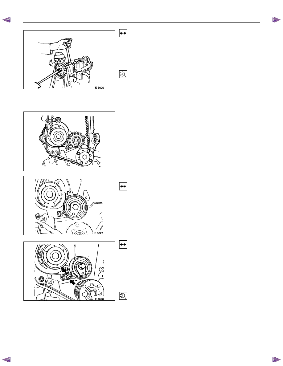
2. Install camshaft pulley while counterholding at camshaft
hex head.
3. Install camshaft housing cover.
Tighten (Torque)
Toothed belt rear cover to oil pump and camshaft housing - 6
N
⋅m/4 lbf ft.
Camshaft housing cover to housing - 6 N
⋅m (0.6 kgf⋅m).
Camshaft pulley to camshaft - 45 N
⋅m (4.6 kgf⋅m).
4. Install toothed belt drive gear to crankshaft - 130 N
⋅m
(13.3 kgf
⋅m).
5. Install toothed belt according to the operation "Toothed
Belt".
Toothed Belt Tension Roller
Removal
1. Mark operating direction of toothed belt.
2. Remove toothed belt according to the operation "Toothed
Belt”.
3. Remove toothed belt tension roller (1) from oil pump.
Installation
1. Install toothed belt tension roller and make sure that the
locking lever (1) engages in the guide lugs (arrowed) on
the oil pump housing.
2. Install toothed belt according to the operation "Toothed
Belt" with paying attention to the operating direction of
toothed belt.
Tighten (Torque)
Toothed belt tension roller to oil pump - 25 N
⋅m (2.5 kgf⋅m)
6A-32 ENGINE MECHANICAL (C24SE)
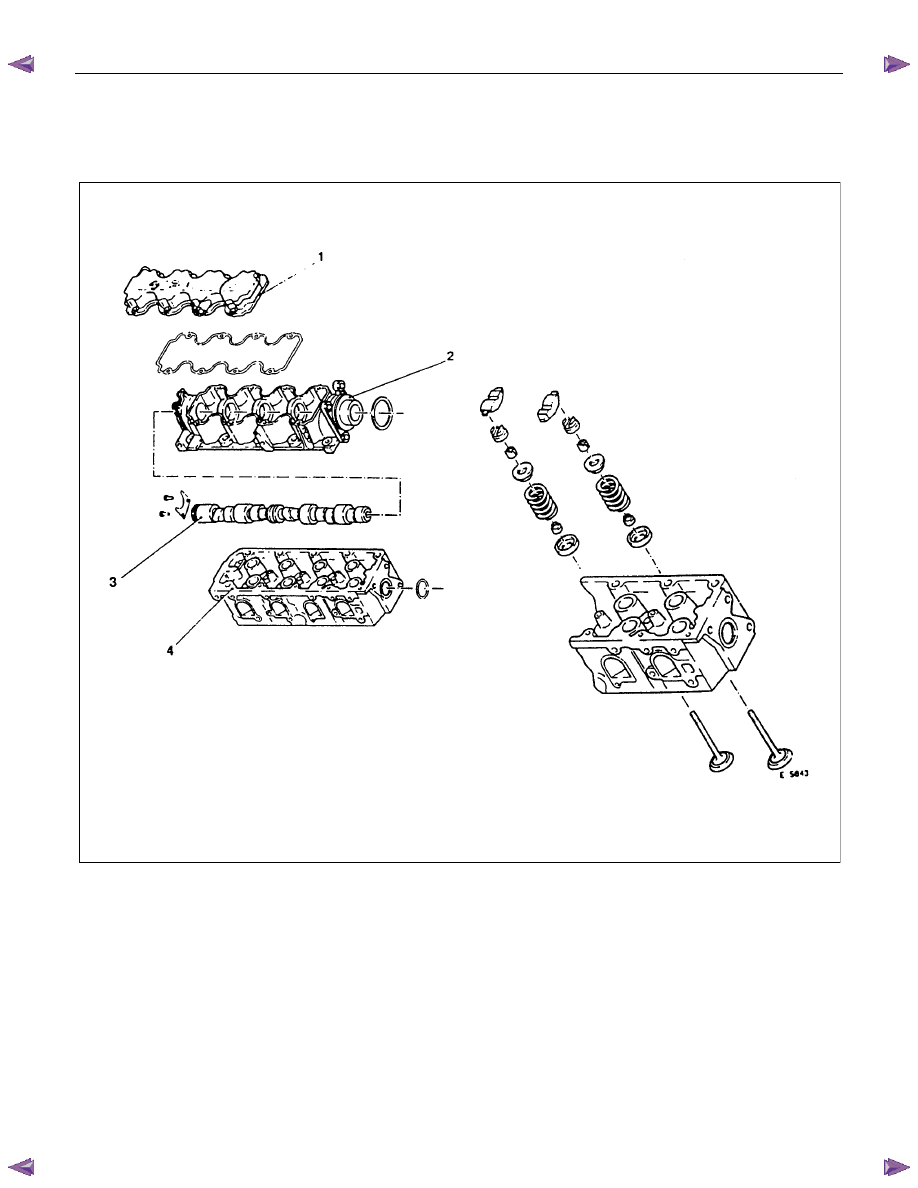
COMPONENT PARTS
CYLINDER HEAD
(A)
1. Camshaft Housing Cover
2. Camshaft Housing
3. Camshaft
4. Cylinder Head
(A) Valve
Drive
ENGINE MECHANICAL (C24SE) 6A-33
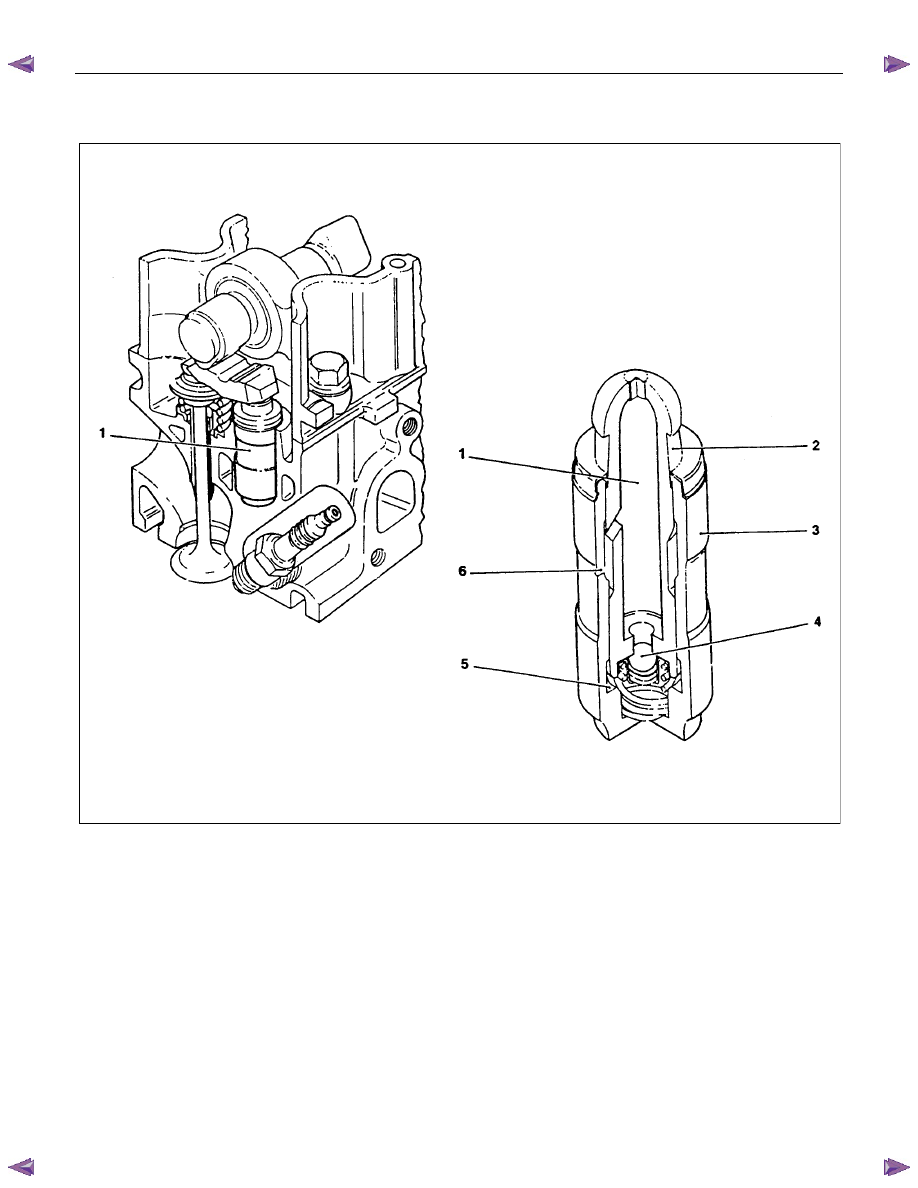
HYDRAULIC VALVE LIFTER
1. Hydraulic Valve Lifter
1. Oil reservoir
2. Piston with ball head (moving)
3. Pressure cylinder (fixed)
4. Check ball
5. Pressure chamber
6. Oil feed
Нет комментариевНе стесняйтесь поделиться с нами вашим ценным мнением.
Текст