Isuzu KB P190. Manual — part 1056
UNIT REPAIR (AW30–40LE)
7A4–89
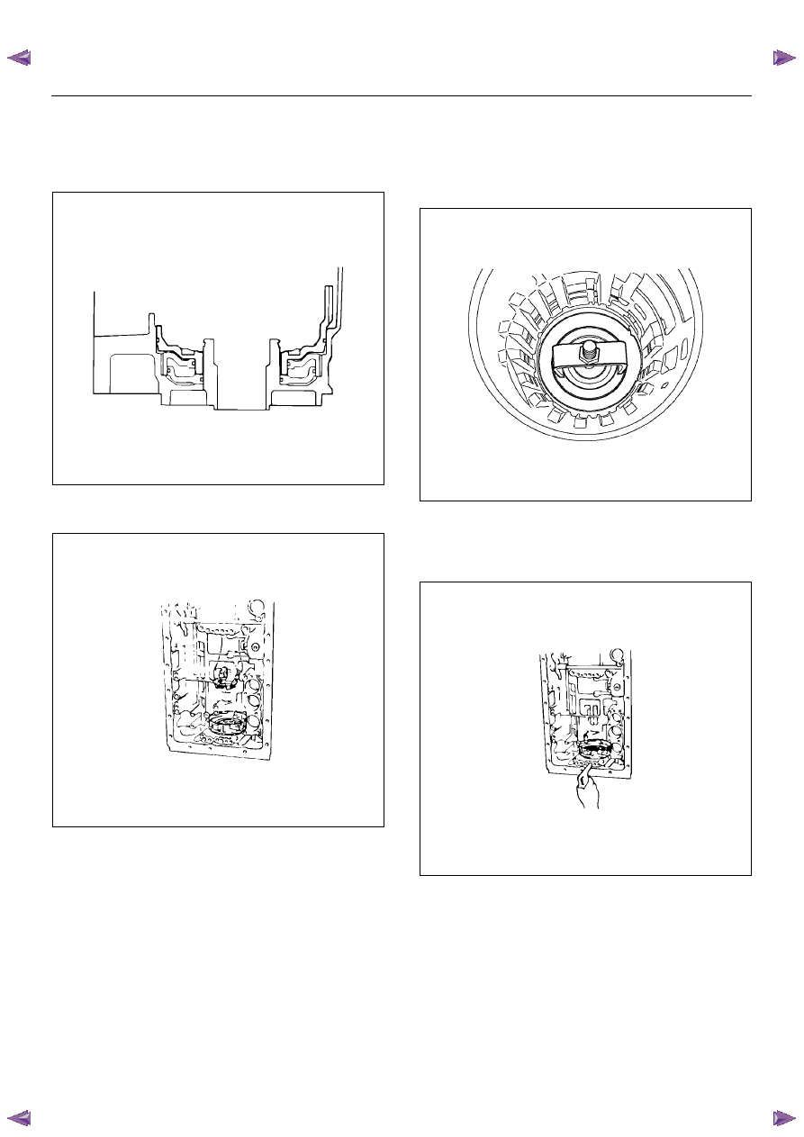
6. Align the teeth of the first and reverse brake piston
No.2 into the proper grooves.
Being careful not to damage the O-rings, press in
the first and reverse brake piston No.2 with No.1
into the transmission case.
246RY00020
7. Place piston return spring onto first and reverse
brake piston No.2.
246RY00021
8. Set special tool as shown, and compress the return
spring with special tool.
Spring compressor: 5-8840-0254-0
Install the snap ring with snap ring pliers.
Be sure the end gap of the snap ring is not aligned
with the spring retainer claw.
247RY00002
9. Check first and reverse brake piston movement.
Make sure the first and reverse brake piston moves
smoothly when applying and releasing the
compressed air into the transmission case.
246RY00022
7A4–90
UNIT REPAIR (AW30–40LE)
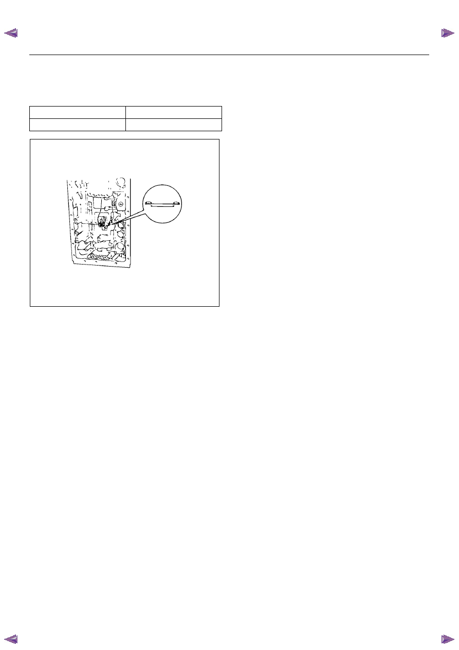
10. Coat the assembled bearing and race with
petroleum jelly.
Install the assembled bearing and race facing the
bearing side upward.
Bearing and race diameter (Reference)
247RY00043
Inside diameter
39.38 mm (1.550 in)
Outside diameter
58.15 mm (2.289 in)
UNIT REPAIR (AW30–40LE)
7A4–91
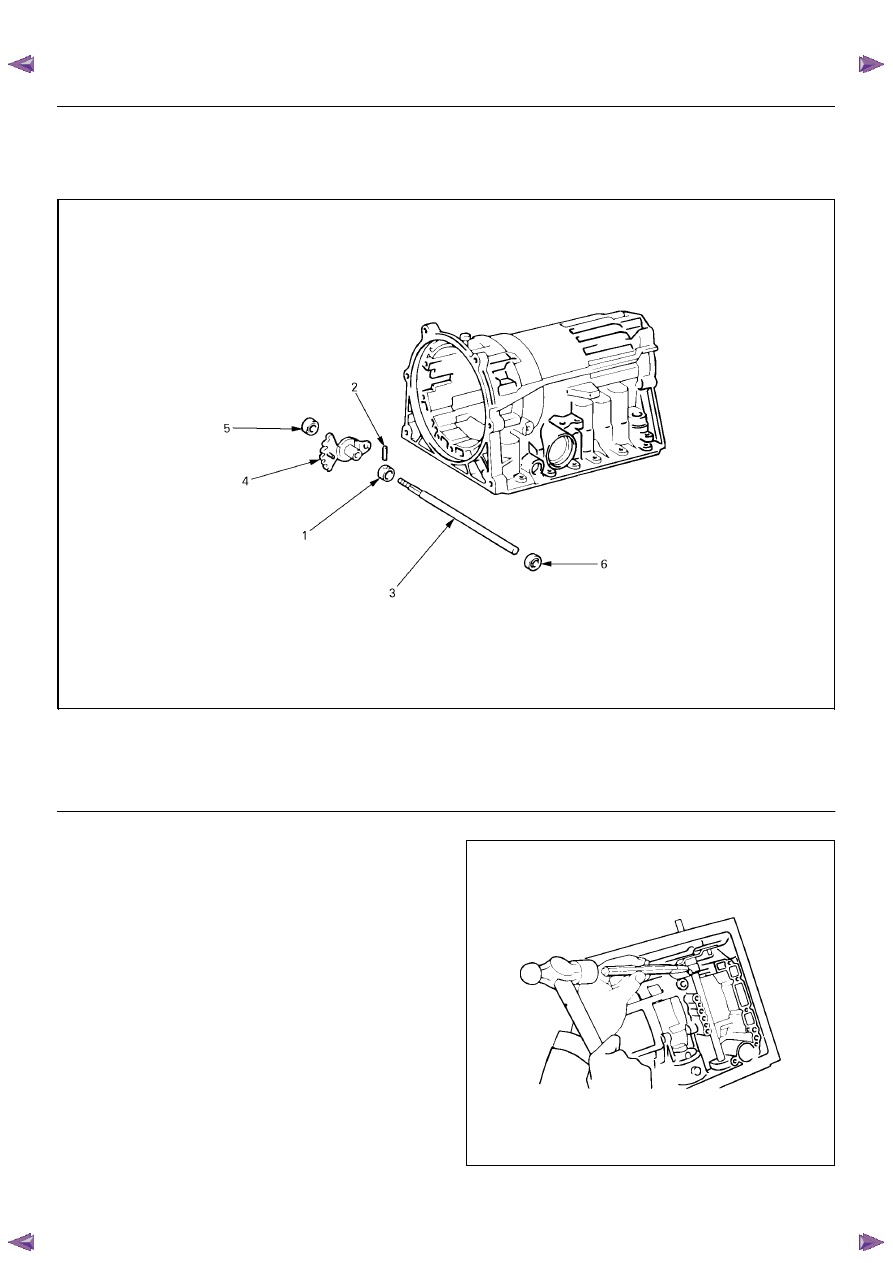
Transmission Case
Disassembled View
249RY00001
EndOFCallout
Disassembly
1. Using a chisel, cut off the spacer and remove it from
the shaft.
249RY00002
Legend
(1) Spacer
(2) Pin
(3) Manual valve lever shaft
(4) Manual valve lever
(5) Oil seal
(6) Oil seal
7A4–92
UNIT REPAIR (AW30–40LE)
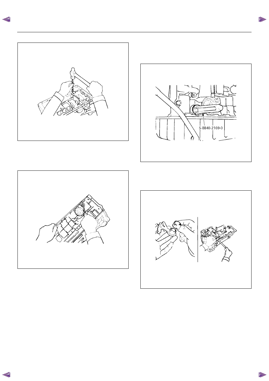
2. Using a punch, drive out the pin.
249RY00003
3. Pull the manual valve lever shaft out through the
case by the threads.
4. Take out the manual valve lever.
5. Using a screwdriver, remove the oil seals.
249RY00004
Reassembly
1. Coat a new oil seal lip with multi purpose grease.
Using special tool, drive in the oil seal.
Oil seal installer : 5-8840-2169-0
240RY00021
2. Assemble a new spacer to the manual valve lever.
3. Install the manual valve lever shaft to the
transmission case through the manual valve lever by
the threads.
249RY00005
Нет комментариевНе стесняйтесь поделиться с нами вашим ценным мнением.
Текст