Isuzu KB P190. Manual — part 344
6A-16 ENGINE MECHANICAL (4JK1/4JJ1)
RTW76ASH001401
14. Remove the breather hose and lower hose of the
radiator.
15. Remove the fan guide.
16. Remove the drive belt.
17. Remove the fan assembly.
18.Remove the radiator.
19.Remove the A/C compressor.
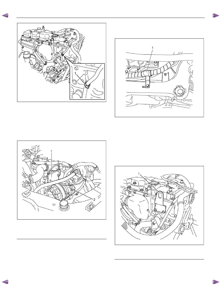
RTW76ASH000701
Legend
1. A/C Compressor Bracket
2. A/C
Compressor
• Disconnect the connector.
• Disconnect the A/C generator harness.
• Disconnect the terminal B cable and harness
connector from the generator.
20.Remove the power steering pump.
• Remove the bracket of power steering oil hose
(1).
LTW56ASH000101
21.Remove the harness of engine, battery and earth
from the body side.
22.Remove the connector of the shift on the fly (4
×4).
23.Remove the vacuum hose of brake master-vac.
24.Remove the front exhaust pipe.
25.Disconnect the fuel hose on the feed and return
sides.
26.Install the engine hanger (special tool 5-8840-
2823-0).
RTW56ASH004301
Legend
1. Engine Hanger (Front Side)
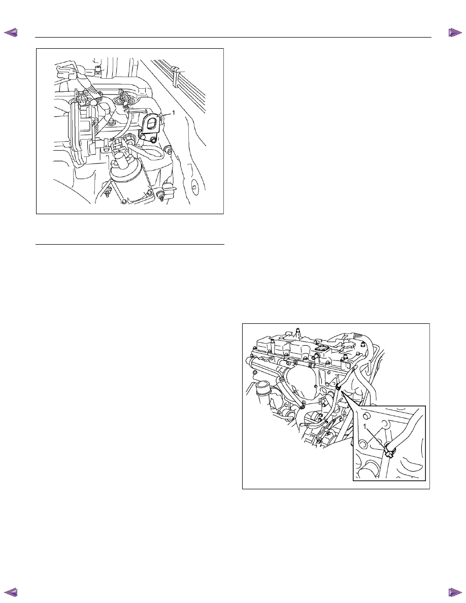
ENGINE MECHANICAL (4JK1/4JJ1) 6A-17
RTW56ASH004401
Legend
1. Engine Hanger (Rear Side)
27.Hang wire on the engine hanger and hoist to lift up
the engine slightly.
28.Remove the engine mount.
• Remove the fastening bolts for the engine mount
on the engine side.
29.Remove the engine assembly.
• Hoist the engine slightly to provide space to
remove the catalytic converter.
Installation
Notice:
Be absolutely sure that each harness is reconnected to
its original position.
1. Install the engine assembly.
• Hang wire on the engine hanger and hoist to lift up
the engine.
• Operate a hoist slowly to move the engine to the
place where it is to be installed.
• Make the transmission side lower and operate a
hoist slowly, pulling it backward to the engine.
2. Install the engine mount.
Tightening torque: 48 N
⋅⋅⋅⋅m (4.9kg⋅⋅⋅⋅m / 35 lb ft)
3. Remove the engine hanger.
4. Install the catalytic converter.
Tightening torque: 27 N
⋅⋅⋅⋅m (2.8kg⋅⋅⋅⋅m /20 lb ft)
5. Install the front exhaust pipe.
Tightening torque: 67 N
⋅⋅⋅⋅m (6.8kg⋅⋅⋅⋅m / 49 lb ft)
6. Install the fuel hose on the feed and return sides.
7. Install the vacuum hose of brake master-vac.
8. Install the connector of the shift on the fly (4
×4).
9. Install the harness of engine, battery and earth to
the body side.
10.Install the power steering pump.
Tightening torque: 25 N
⋅⋅⋅⋅m (2.5kg⋅⋅⋅⋅m / 18 lb ft)
• Install the bracket of power steering oil hose.
11.Install the A/C compressor.
Tightening torque: 25 N
⋅⋅⋅⋅m (2.5kg⋅⋅⋅⋅m / 18 lb ft)
• Install the connector.
12.Install the A/C generator harness.
• Install the terminal B cable and the harness
connector to the generator.
13.Install the radiator.
Tightening torque: 25 N
⋅⋅⋅⋅m (2.5kg⋅⋅⋅⋅m / 18 lb ft)
14.Install the fan assembly.
Tightening torque: 8 N
⋅⋅⋅⋅m (0.8kg⋅⋅⋅⋅m / 69 lb in)
15.Install the drive belt.
Refer to removal procedure for drive belt in this
manual.
16.Install the fan guide.
17.Install the breather hose and lower hose of the
radiator.
18.Install the engine harness clip (1).
RTW76ASH001401
19.Install the radiator upper hose.
20.Install the intake hose (turbocharger -intercooler)
(Standard output).
• Install the harness connector.
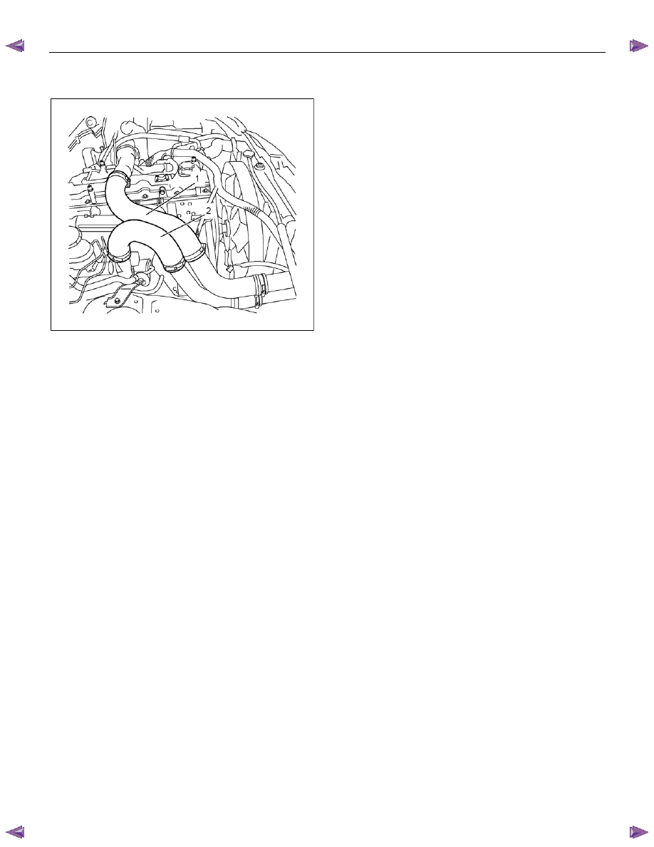
6A-18 ENGINE MECHANICAL (4JK1/4JJ1)
21.Install the intake hose (intercooler - intake throttle)
(Standard output).
RTW56ASH004001
22.Install the intercooler (High output).
• Install the intercooler.
• Install the two intake hoses.
• Connect the BARO sensor harness connector.
23.Install the air cleaner.
• Install the intake pipe with the lid of air cleaner
box.
• Install the air cleaner box.
• Connect the MAF sensor harness connector.
24.Install the ECM.
25.Connect the ECM harness connector.
26.Install the transmission assembly.
Refer to installation procedure for
“TRANSMISSION”.
27.Install the starter motor.
Tightening torque: 94 N
⋅⋅⋅⋅m (9.6kg⋅⋅⋅⋅m / 69 lb ft)
28.Replenish the coolant.
29.Install the engine hood.
Tightening torque: 10 N
⋅⋅⋅⋅m (1.0kg⋅⋅⋅⋅m / 87 lb in)
30.Connect the negative battery cable.
ENGINE MECHANICAL (4JK1/4JJ1) 6A-19
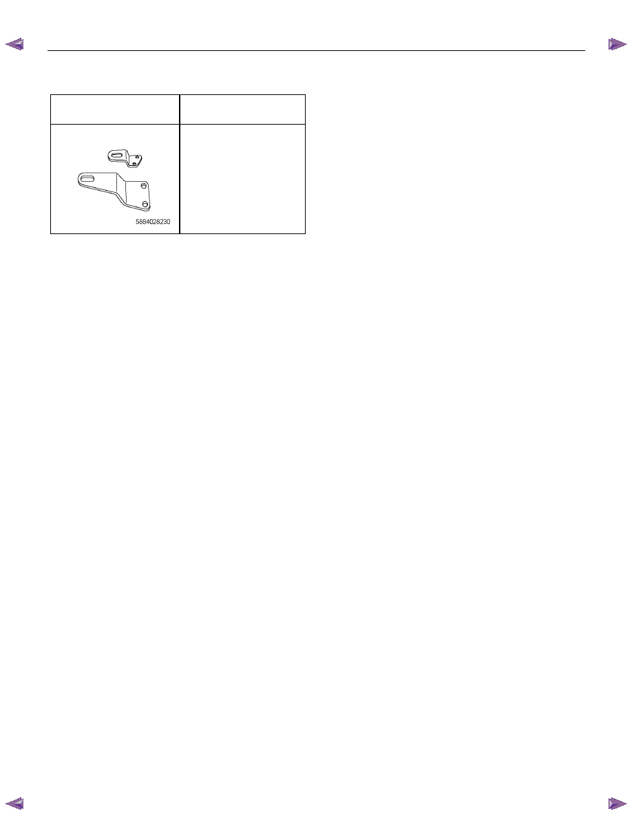
Special Tools
ILLUSTRATION
PART NO.
PART NAME
5-8840-2823-0
Engine hanger
Нет комментариевНе стесняйтесь поделиться с нами вашим ценным мнением.
Текст