Isuzu KB P190. Manual — part 360

6A-80 ENGINE MECHANICAL (4JK1/4JJ1)
49. Remove the timing chain tension lever pivot.
RTW56ASH019401
50.
Remove the timing chain from supply pump
sprocket.
51. Remove the chain guide bolt from cylinder head.
RTW56ASH019501
52. Remove the cylinder head gear case nuts (1) and
bolts (2).
RTW56ASH020801
53. Remove the cylinder head bolt (1).
RTW56ASH008501
Note:
Do not reuse the cylinder head bolt.

ENGINE MECHANICAL (4JK1/4JJ1) 6A-81
54. Remove the cylinder head assembly.
• Loosen the cylinder head bolts in the order
described in the drawing.
• Remove the cylinder head gasket.
Note:
Replace the head gasket with a new one once it is
removed.
RTW56ASH008601
Disassembly
1. Remove the throttle assembly.
• Refer to procedure for Intake Manifold in this
manual.
2. Remove the intake manifold assembly.
• Refer to procedure for Intake Manifold in this
manual.
3. Remove the turbocharger.
• Refer to “Turbocharger and Exhaust Manifold”.
4. Remove the exhaust manifold assembly.
• Refer to procedure for Turbocharger and
Exhaust Manifold in this manual.
5. Remove the water outlet pipe.
6. Remove the valve stem cap.
Refer to procedure for valve stem and valve in this
manual.
7. Remove the split collar.
• Use a replacer to compress the valve spring to
remove the split collar.
Special
tool
Valve spring replacer: 5-8840-2818-0 (1)
Pivot assembly: 5-8840-2819-0 (2)
RTW56ASH012301
8. Remove the spring upper seat.
• Remove the special tool to remove the upper
seat.
9. Remove the valve spring.
• Put the removed valve springs in order by
cylinder number.
6A-82 ENGINE MECHANICAL (4JK1/4JJ1)
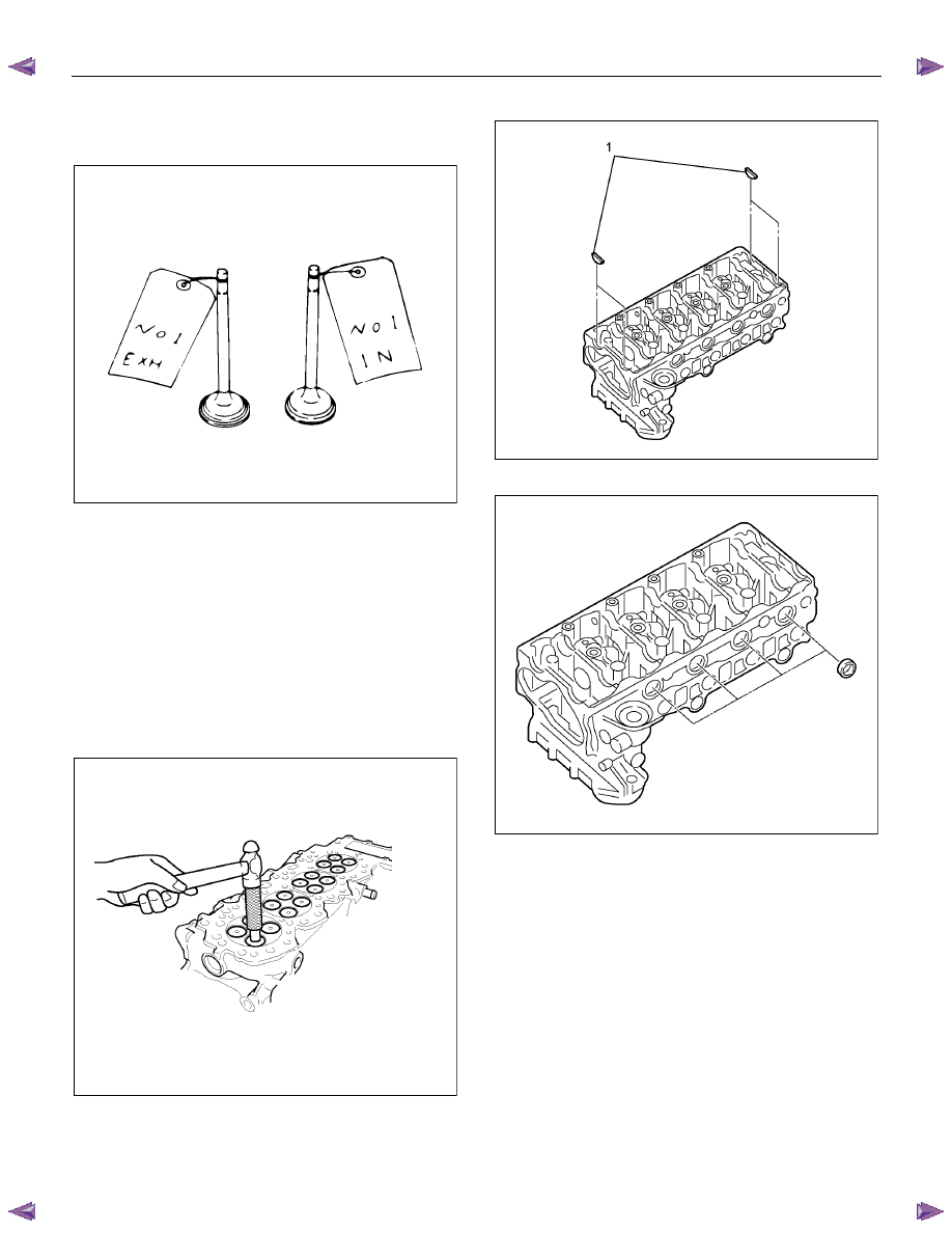
10. Remove the intake and exhaust valve.
• Sort the removed valves according to cylinders
by using tags others.
LNW21BSH016801
11. Remove the valve stem oil seal.
• Refer to procedure for valve stem and valve in
this manual.
12. Remove the spring lower seat.
13. Remove the valve guide.
• Use the valve guide replacer to press out the
valve guides from the bottom side of the
cylinder head.
Special
tool
Valve guide remover and installer:
5-8840-2816-0
RTW56ASH008701
14. Remove the cam end gasket (1).
RTW56ASH020501
15. Remove the oil seal.
RTW56ASH008801
ENGINE MECHANICAL (4JK1/4JJ1) 6A-83
Inspection
Make the necessary adjustments, repairs, and part
replacements if excessive wear or damage is
discovered during inspection.
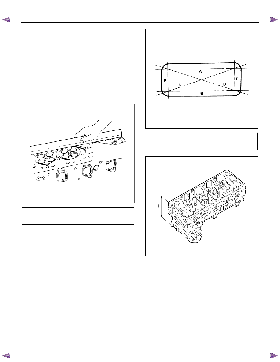
Cylinder Head Lower Face Warpage
1. Use a straight edge and a thickness gauge to
measure the four sides and the two diagonals of
the cylinder head lower face.
2. The cylinder head lower surface warpage is more
than the limit, it should be replaced.
RTW56ASH008901
Cylinder Head Lower Face Warpage
mm (in)
Standard
0.05 (0.002) or less
Limit 0.20
(0.0079)
NOTE:
The cylinder head lower face cannot be regrind.
011RY00013
Cylinder Head Height (H) (Reference)
mm (in)
Standard 143.4
(5.646)
RTW56ASH017401
Manifold Fitting Face Warpage
Use a straight edge and a feeler gauge to measure the
manifold cylinder head fitting face warpage.
Regrind the manifold cylinder head fitting surfaces if the
measured values are greater than the specified limit but
less than the maximum grinding allowance.
If the measured values exceed the maximum grinding
allowance, the cylinder head must be replaced.
Нет комментариевНе стесняйтесь поделиться с нами вашим ценным мнением.
Текст