Isuzu KB P190. Manual — part 564
6E–86
ENGINE DRIVEABILITY AND EMISSIONS
5. After choosing the data, click the “Next” button.
6. When all the necessary information is entered, the
“details” of software within the database that match
the entered data will appear for confirmation. Click
the “Program” switch and then download the new
software onto Tech-2.
7. “Data Transfer” comes on display. The progress of
downloading will be displayed on the screen in the
form of bar graph.
8. Upon finishing the data transfer, turn off the power
of Tech-2, removing from P/C.
4. Programming of ECM
1. Check to see if batteries are fully charged, while
ABS connectors shall be removed from the vehicle.
2. Connect Tech-2 to Vehicle Diagnostic Connectors.
3. Turn on the power of Tech-2 and the title screen
comes on display.
4. Turn on the ignition (without allowing the engine to
start)
5. On the title screen of Tech-2, push the “Enter”
button.
6. Choose “F1: Service Programming System” on the
main screen and then choose “Fl: Program ECU”.
7. While data is being transferred, “Programming in
Progress” will be displayed on the Tech-2 screen.
8. Upon finishing the data transfer, Tech-2 will display
“Reprogramming Was Successful”. Push the “Exit”
button to bring program to completion
9. Following “Procedure 2: Demand of Data”, try over
again “Information Obtaining” and check to confirm
if the data has been correctly re-loaded.
10. Upon finishing confirmation, turn off the ignition of
the vehicle and then turn off the power of Tech-2,
removing from the vehicle.
ENGINE DRIVEABILITY AND EMISSIONS
6E–87
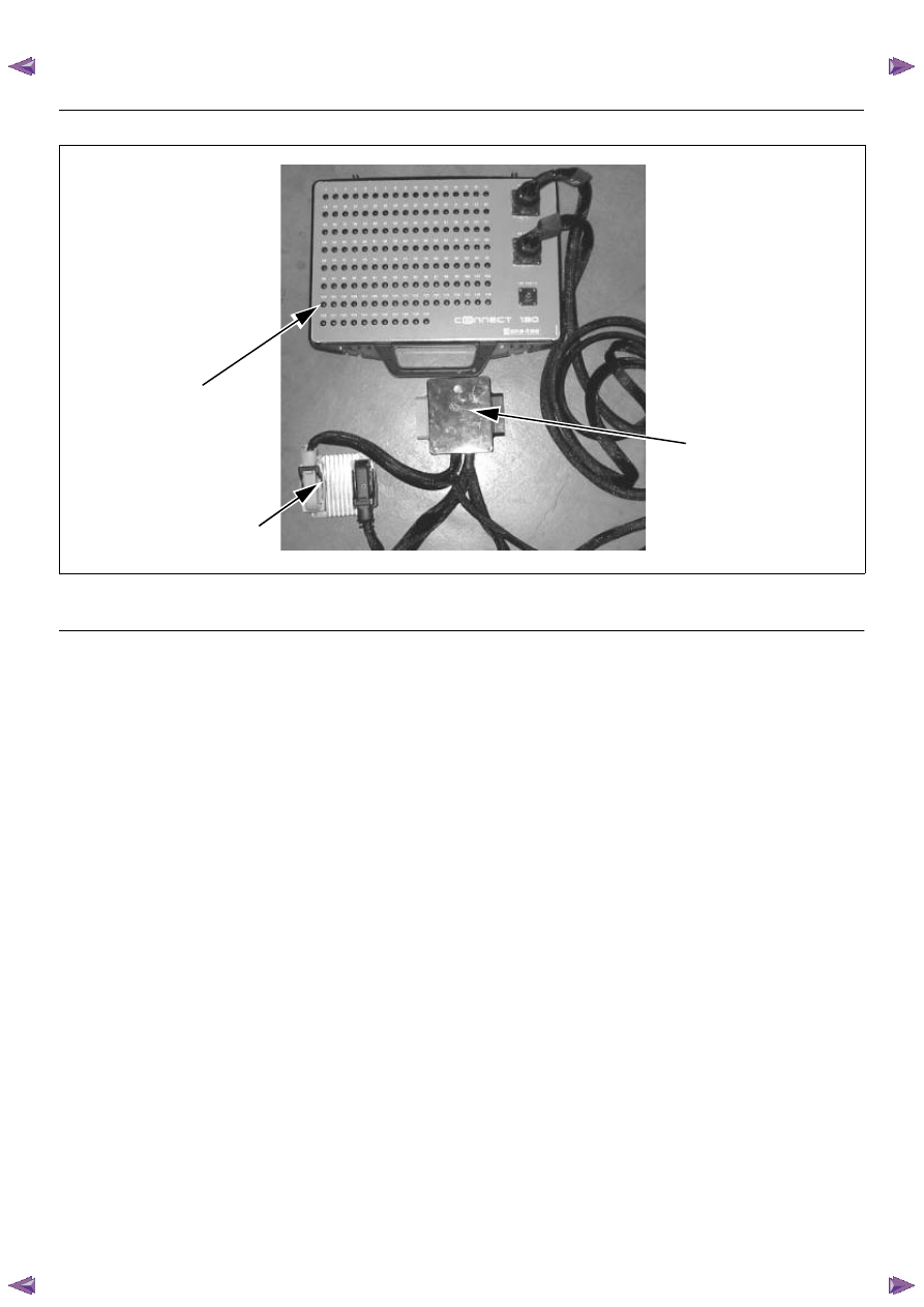
HOW TO USE BREAKER BOX
The engine control module (ECM) and other connectors
have water proof connector and special terminal. Water
proof terminal does not allow to use back prove. In
addition, the engine control module (ECM) special
terminal can not let regular digital voltage meter prove
to access, because terminal shape is very fin pin type.
In order to prevent damage of female terminal and
connector itself, the breaker box and adapter is the
most suitable special tool.
3
1
2
(1) Engine Control Module (ECM)
(2) Harness Adapter
(3) Breaker Box

6E–88
ENGINE DRIVEABILITY AND EMISSIONS
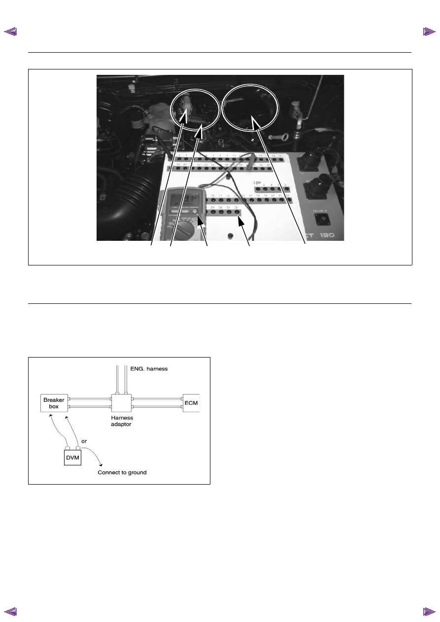
Breaker Box Connection Type A
Breaker box connection type A, check for “open circuit”
and “short to ground circuit”.
5
1
4
3
2
(1) Engine Control Module (ECM)
(2) Harness Adapter
(3) Breaker Box
(4) Digital Voltage Meter
(5) ECM - Harness Adapter Disconnection
ENGINE DRIVEABILITY AND EMISSIONS
6E–89
Breaker Box Connection Type B
Breaker box connection type B, check for “short to
power supply circuit” and “power, signal voltage check”
between the engine control module (ECM) and
electrical components.
5
1
4
3
2
(1) Engine Control Module (ECM)
(2) Harness Adapter
(3) Breaker Box
(4) Digital Voltage Meter
(5) ECM - Harness Adapter Connection
Нет комментариевНе стесняйтесь поделиться с нами вашим ценным мнением.
Текст