Isuzu KB P190. Manual — part 1172
7B1-82 MANUAL TRANSMISSION
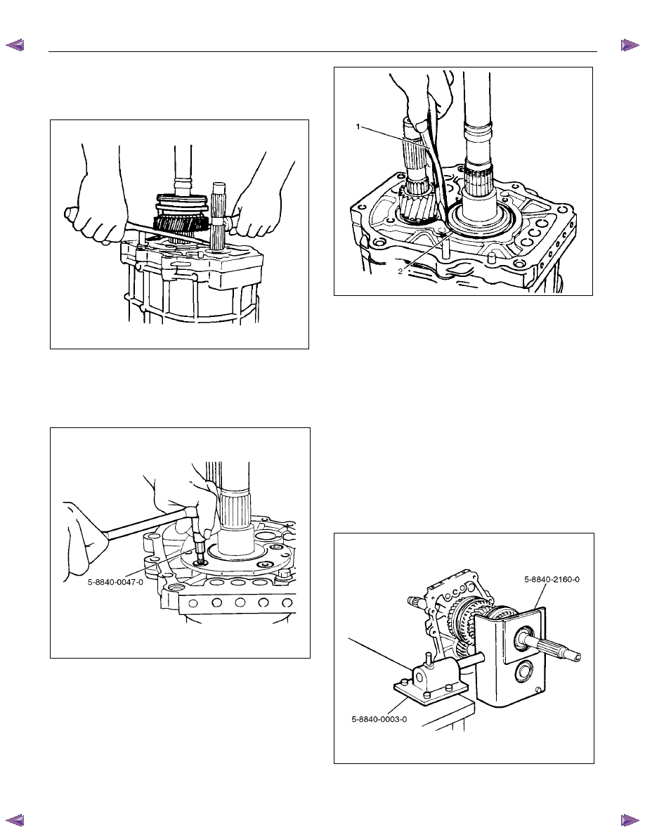
13. Use screw drivers between the reverse gear and the
bearing plate to remove the Rev-5th synchronizer
assembly together with the reverse block ring and
reverse gear.
226RS010
14. Remove the needle bearing.
15. Use the torx bit wrench (T- 45) 5-8840-0047-0 to
remove the bearing plate and screw from the
intermediate plate.
220RW137
16. Use the snap ring pliers (1) to remove the mainshaft
bearing snap ring (2).
226RS011
17. Hold the snap ring open with the pliers.
Push the intermediate plate toward the rear of the
transmission to remove it.
The bearing snap ring will come free.
Inspection and Repair
Refer to Top Gear Shaft, Main Gear Shaft, and Counter
Gear in this section for inspection and repair.
Reassembly
1. Mesh the counter gear with the mainshaft assembly.
Set the holding fixture 5-8840-2160-0 to the
mainshaft and the counter gear and then install it on
the base 5-8840-0003-0.
Install the intermediate plate on the gear assembly.
226RW212
MANUAL TRANSMISSION 7B1-83
2. Install the bearing snap ring.
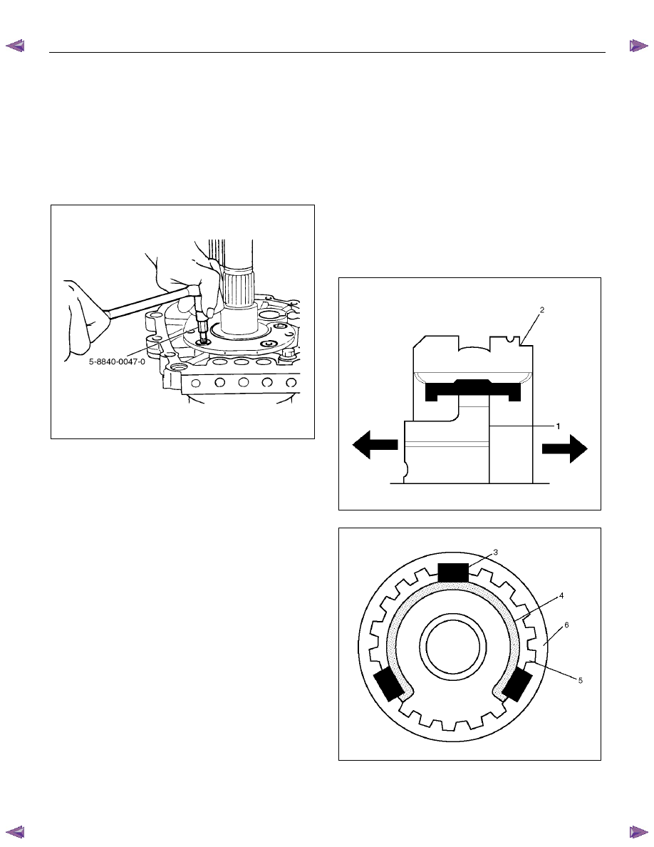
3. Apply recommended thread locking agents
(LOCTITE 242) or equivalent to each of the bearing
plate screw threads.
Install the bearing plate and screw.
Tighten the screws to the specified torque by using
torx bit wrench (T- 45) 5-8840-0047-0.
Torque: 15 N
⋅⋅⋅⋅m (1.5 kgf⋅⋅⋅⋅m/11 lb⋅⋅⋅⋅ft)
220RW137
4. Install the needle bearing, reverse gear and reverse
block ring.
5. Assemble the rev-5th synchronizer assembly by
performing the following steps.
1. Turn the clutch hub face (1) toward the sleeve
groove (2) (rear side) on the outer
circumference.
2. Check that the inserts (3) fit snugly into the
clutch hub (5) ring insert grooves.
3. Check that the inserts springs (4) are fitted to
the inserts as shown in the illustration.
4. Check that the clutch hub (5) and the sleeve (6)
slide smoothly.
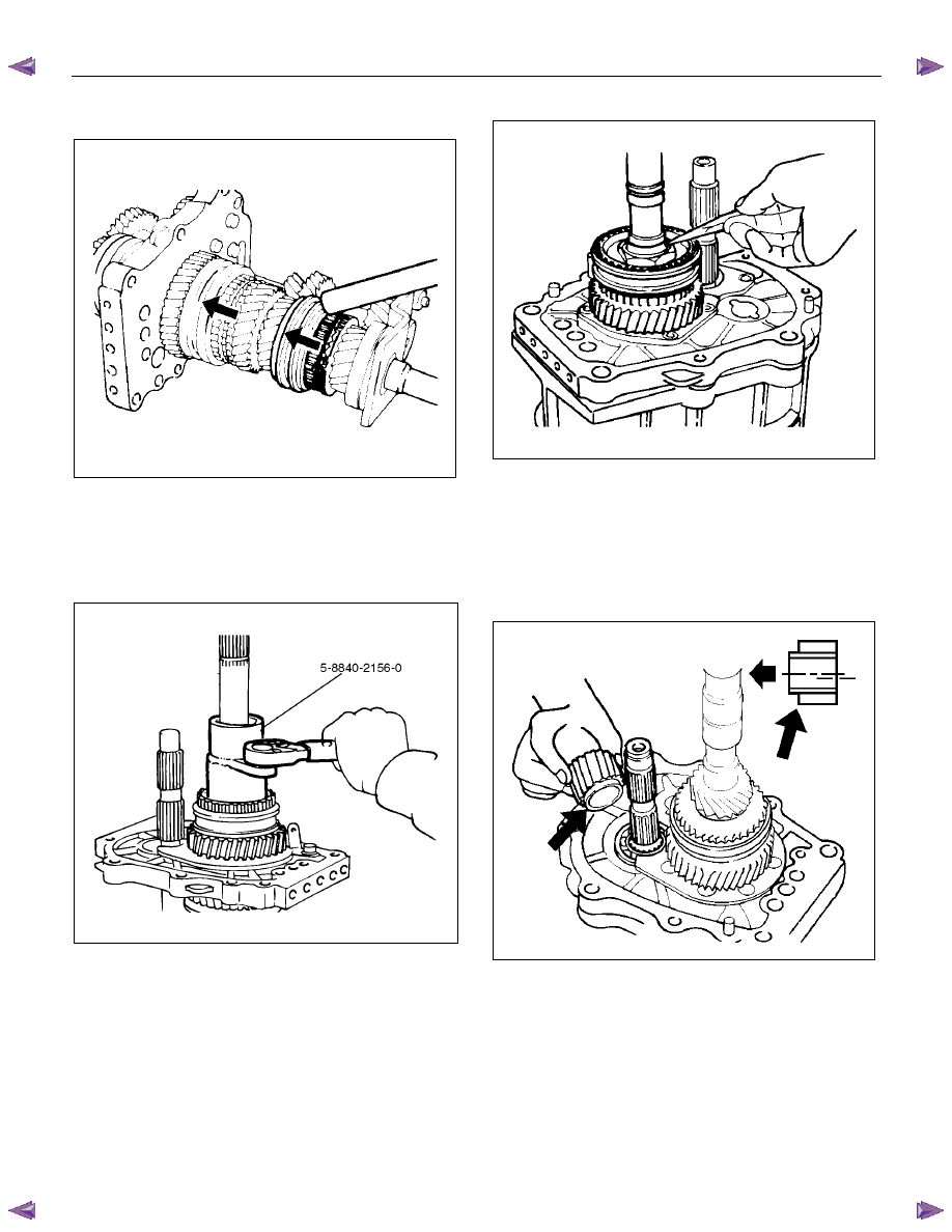
5. Install the synchronizer assembly to the
mainshaft.
The clutch hub face with the heavy boss must be
facing the reverse gear side.
226RS013
226RS049
7B1-84 MANUAL TRANSMISSION
6. Mesh the 1st-2nd and 3rd-4th synchronizers with
both the 1st and 3rd gears (double engagement).
226RS015
This will prevent the mainshaft from turning.
7. Install the new mainshaft hub nut.
Use the mainshaft nut wrench 5-8840-2156-0 to
tighten the mainshaft nut to the specified torque.
Torque: 137 N
⋅⋅⋅⋅m (14.0 kgf⋅⋅⋅⋅m/101 lb⋅⋅⋅⋅ft)
226RW214
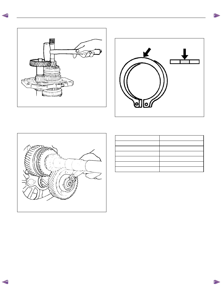
8. Use a punch to stake the mainshaft nut.
226RW153
9. Install the needle bearing, 5th block ring, and 5th
gear.
10. Apply engine oil to the counter reverse gear and the
reverse gear.
Install the counter reverse gear to the counter shaft.
The reverse gear projection must be facing the
intermediate plate.
226RW151
MANUAL TRANSMISSION 7B1-85
11. Install the counter 5th gear to the counter shaft.
226RS019
12. Install the ball bearing and bearing snap ring by
performing the following steps:
• Select the snap ring which will provide the
minimum clearance between the ball bearing
and the snap ring.
226RS020
• There are six snap ring sizes available.
The snap rings are color‐ coded to
indicate their thickness.
226RS021
Ball Bearing and Snap Ring Clearance
Standard: 0 - 0.15 mm (0 - 0.0059 in)
Snap Ring Availability
Thickness Color
Coding
1.1 mm (0.043 in)
White
1.2 mm (0.047 in)
Yellow
1.3 mm (0.051 in)
Blue
1.4 mm (0.055 in)
Pink
1.5 mm (0.059 in)
Green
1.6 mm (0.063 in)
Brown
• Use a pair of snap ring pliers to install the snap
ring to the counter gear shaft.
The snap ring must be fully inserted into the
counter gear shaft snap ring groove.
13. Assemble the reverse idler shaft, reverse idler gear,
thrust washer, and idle shaft pin into the reverse
idler gear assembly.
The thrust washer should be assembled with the oil
groove faces to gear side.
Нет комментариевНе стесняйтесь поделиться с нами вашим ценным мнением.
Текст