Isuzu KB P190. Manual — part 904
Starting System – V6
Page 6D1-2–8
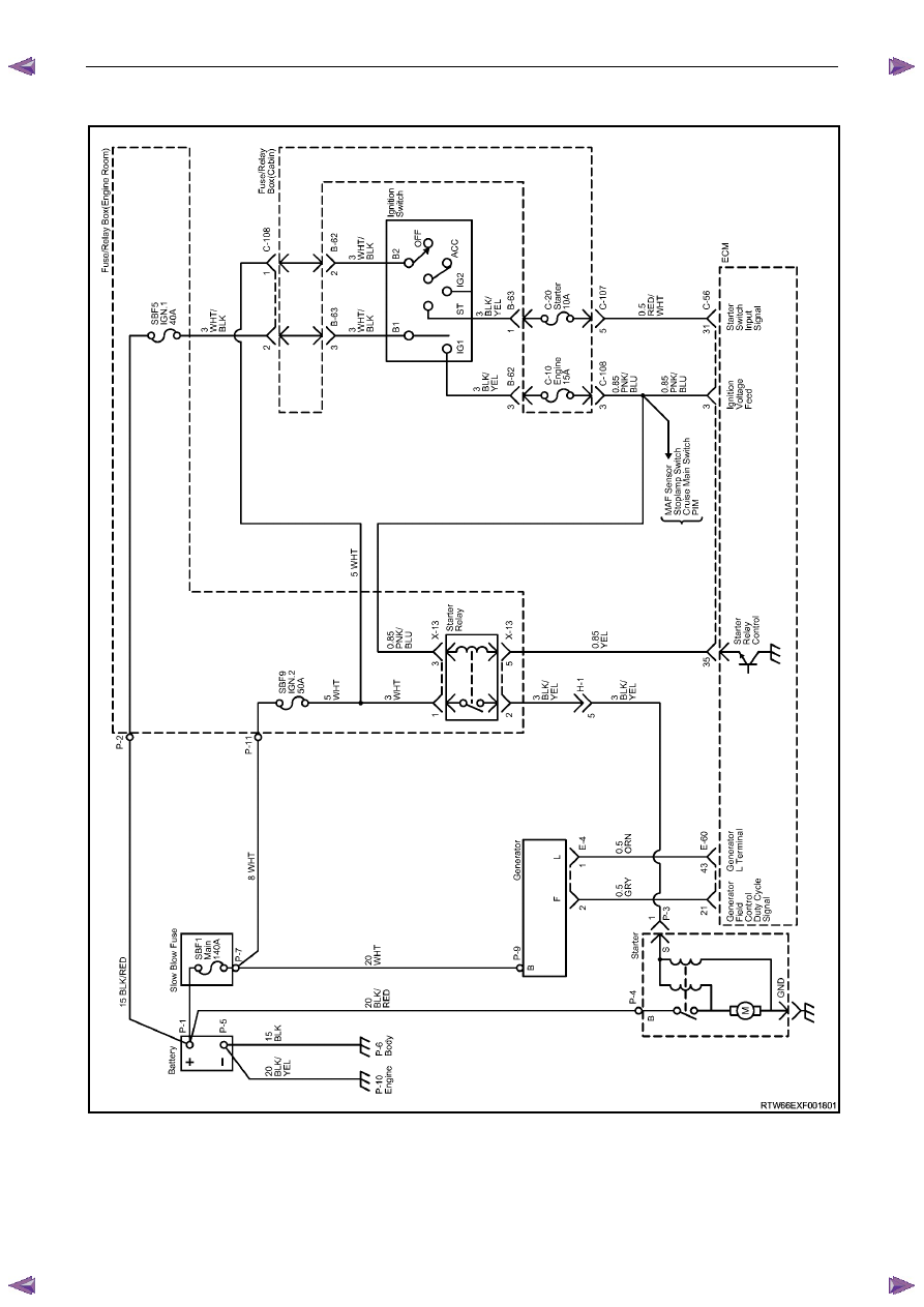
2.4 Wiring
Diagram
Figure 6D1-2 – 2
Starting System – V6
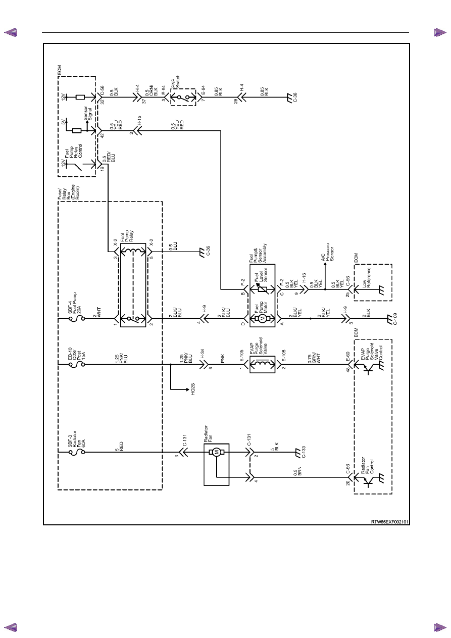
Page 6D1-2–9
Figure 6D1-2 – 3

Starting System – V6
Page 6D1-2–10
2.5
Starting System Inoperative /
Malfunctioning
Circuit Description
The battery cable supplies a constant connection from the battery to starter solenoid connector P – 4.
When the ignition switch is turned to the START position, 12 V is applied to the ECM connector C – 56 pin 31.
For vehicles with 4 speed automatic transmission, when the transmission is in park (P) or neutral (N), the park / neutral
and back-up switch grounds ECM connector C – 56 pin 32.
The ECM provides a ground for the start relay, ECM connector C – 56 pin 35 to start relay connector X – 13 pin 5.
When activated the start relay provides 12 V to starter solenoid connector P – 3 pin 1.
The solenoid closes its switch contacts to connect the battery voltage at the solenoid switch terminal P – 4 terminal B to
the DC motor. The pull-in winding of the solenoid switch is grounded through the DC motor winding and brushes. The
hold-in winding is grounded through the solenoid casing. The DC motor is grounded through the starter motor casing.
Refer to 2.4
Wiring Diagram to aid in diagnosis.
Diagnostic Table Notes
Reference to following information will assist when diagnosing starting circuit faults:
1
If the battery, starter motor and fuel system are deemed as serviceable and a ‘no crank’ and / or ‘no start’ condition
exists, refer to the following Sections as required:
a
11A Immobiliser for theft deterrent engine crank inhibitor related faults
b
6C1-2 Engine Management V6 Diagnostics, for starter relay circuit faults
2
For all wiring harness fault diagnoses, refer to 8A Electrical Body and Chassis.
3
For wiring harness repairs, refer to 8A Electrical Body and Chassis.
4
Refer to 8A Electrical Body and Chassis for harness routing.
5
Ensure the battery, cables and connections are in good order. Refer to 8A Electrical Body and Chassis.
Diagnostic Table
Step Action
Yes
No
1
Did you review 1.3
System Operation?
Go to Step 2
Go to 1.3
System
Operation
2
Did you read 2.3 Diagnostic Systems Check
Go to Step 3
Go to 2.3
Diagnostic
Systems Check
3
Turn the ignition switch to the START position and then release it.
Did the engine crank or were there any clicking or chattering sounds
from the solenoid?
Go to Diagnostic
Table – Slow
Cranking, Solenoid
Clicks or Chatters
Go to Step 4
4
Inspect fusible link SBF9, refer to 8A Electrical Body and Chassis.
Is fusible link SBF9 blown?
Replace the faulty
fusible link (refer to
Note 3).
If the fusible link
blows again, repair
or replace the circuit
from SBF9 to the
starter relay X – 13
pin 1 or ignition
switch B – 62 pin 2
(refer to Note 2)
Go to Step 5

Starting System – V6
Page 6D1-2–11
Step Action
Yes
No
5
Inspect fusible link SBF1, refer to 8A Electrical Body and Chassis.
Is fusible link SBF1 blown?
Replace the faulty
fusible link (refer to
Note 3).
If the fusible link
blows again, repair
or replace the circuit
from SBF1
connection P – 7
and engine
compartment fuse
panel connector B –
63 pin 3, (refer to
Note 2)
Go to Step 6
6
Inspect fuse SBF5, refer to 8A Electrical Body and Chassis.
Is fuse SBF5 blown?
Replace the faulty
fuse (refer to
Note 3).
If the fuse blows
again, repair or
replace the circuit
from SBF5 to the
cabin fuse panel
connector C – 108
pin 2 (refer to
Note 2)
Go to Step 7
7
Inspect fuse C20, refer to 8A Electrical Body and Chassis.
Is fuse F15 blown?
Replace the faulty
fuse (refer to
Note 3).
If the fuse blows
again, repair or
replace the circuit
from fuse C20 to the
ECM connector C –
56 pin 31 (refer to
Note 2)
Go to Step 8
8
N O T E
On automatic vehicles ensure that park (P) or neutral (N) is
selected.
Turn the headlamps on.
Turn the dome lamps on.
Turn the ignition switch to the START position.
Do the lamps dim?
Go to Step 9
Go to Step 10
9
Perform the 3.3 On-Vehicle Testing.
Did you correct the condition?
Go to Step 21
Go to Step 2
Нет комментариевНе стесняйтесь поделиться с нами вашим ценным мнением.
Текст