Isuzu KB P190. Manual — part 207
ENGINE MECHANICAL 6A – 23
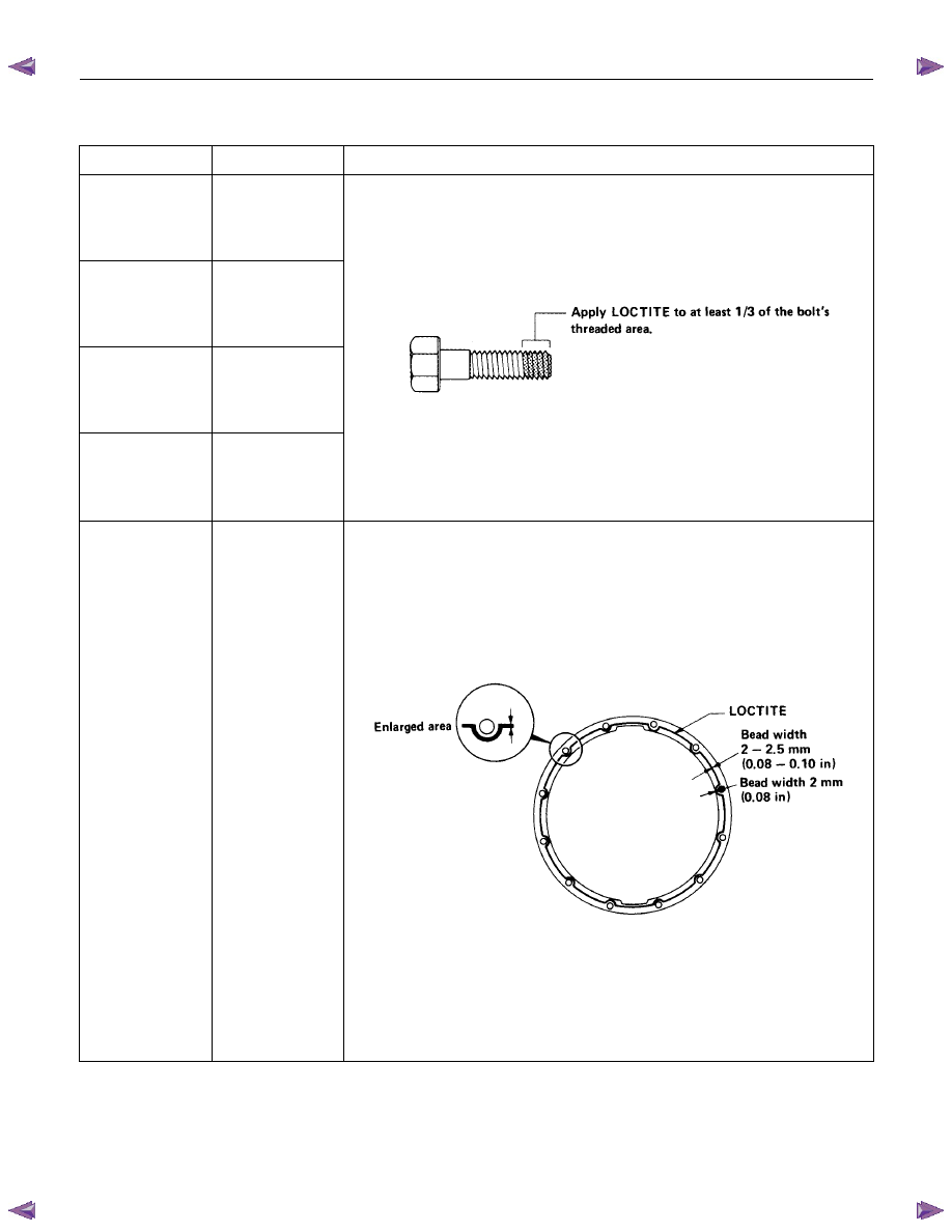
LOCTITE APPLICATION PROCEDURE
LOCTITE Type
LOCTITE Color
Application Steps
LOCTITE 242
Blue
LOCTITE 262
Red
LOCTITE 270
Green
LOCTITE 271
Red
1.
Completely remove all lubricant and moisture from the bolts and the
female threaded surfaces of the parts to be joined.
The surfaces must be perfectly dry.
2.
Apply LOCTITE to the bolts.
3.
Tighten the bolts to the specified torque.
4.
Wait at least one hour before continuing the installation procedure.
LOCTITE 515
Violet
1.
Completely remove lubricant and moisture from the connecting
surfaces.
The surfaces must be perfectly dry.
2.
Apply a 2.0 – 2.5 mm bead of LOCTITE to one of the connecting
surfaces.
There must be no gaps in the bead.
3.
Tighten the bolts to the specified torque.
4.
Let the joined parts set for at least thirty minutes.
6A – 24 ENGINE MECHANICAL
SERVICING
Servicing refers to general maintenance procedures to be performed by qualified service personnel.
RTW36ASH000401
MODEL IDENTIFICATION
Engine Serial Number
The engine number is stamped on the rear left hand side
of the cylinder body.
The engine number is stamped in the plate in front of the
engine room as well.
AIR CLEANER
Element cleaning procedures will vary according to the
condition of the element.
Dust Fouled Element (Except wet type element)
Rotate the element with your hand while applying
compressed air to the inside of the element. This will blow
the dust free.
Compressed air pressure kPa (kg/cm
2
/psi)
392 – 490 (4 – 5/57 – 71)
LUBRICATING SYSTEM
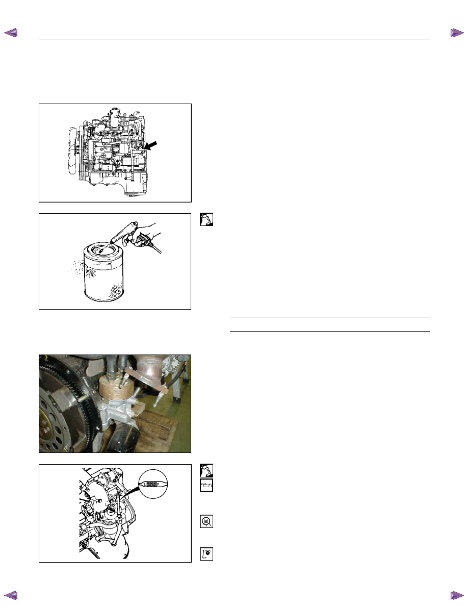
Main Oil Filter (Cartridge Type Paper Element)
Replacement Procedure
1. Drain the engine oil.
2. Retighten the drain plug.
3. Loosen the used oil filter by turning it counterclockwise
with a filter wrench.
Filter Wrench: 5-8840-0200-0
RTW36ASH000101
4. Clean the oil cooler fitting face. This will allow the new
oil filter to seat properly.
5. Apply a light coat of engine oil to the filter O-ring.
6. Turn in the new oil filter until the filter O-ring is fitted
against the sealing face.
7. Use the filter wrench to turn in the filter an additional
2/3 turns.
Filter Wrench: 5-8840-0200-0
8. Check the engine oil level and replenish to the
specified level if required.
130RY00003
6A-6
ENGINE MECHANICAL 6A – 25
Replenished Engine Oil
MAX lit (US/UK gal)
Condition
Model
Engine Dry
With oil filter
replacement
Without oil
filter
replacement
4
× 2
4
× 4
(4JA1L/TC)
6.2 (1.64/1.36)
5.2
∼ 4.2
(1.37
∼ 1.11
/ 1.14
∼ 0.92)
4.5
∼ 3.5
(1.19
∼ 0.93
/ 0.99
∼ 0.77)
4
× 2
(4JH1TC)
6.2 (1.64/1.36)
5.2
∼ 4.2
(1.37
∼ 1.11
/ 1.14
∼ 0.92)
4.5
∼ 3.5
(1.19
∼ 0.93
/ 0.99
∼ 0.77)
4
× 4
(4JH1TC)
7.0 (1.85/1.54)
6.2
∼ 5.2
(1.64
∼ 1.37
/ 1.36
∼ 1.14)
5.3
∼ 4.3
(1.72
∼ 1.14
/ 1.17
∼ 0.95)
9. Start the engine and check for oil leakage from the
main oil filter.
RTW66ASH003201
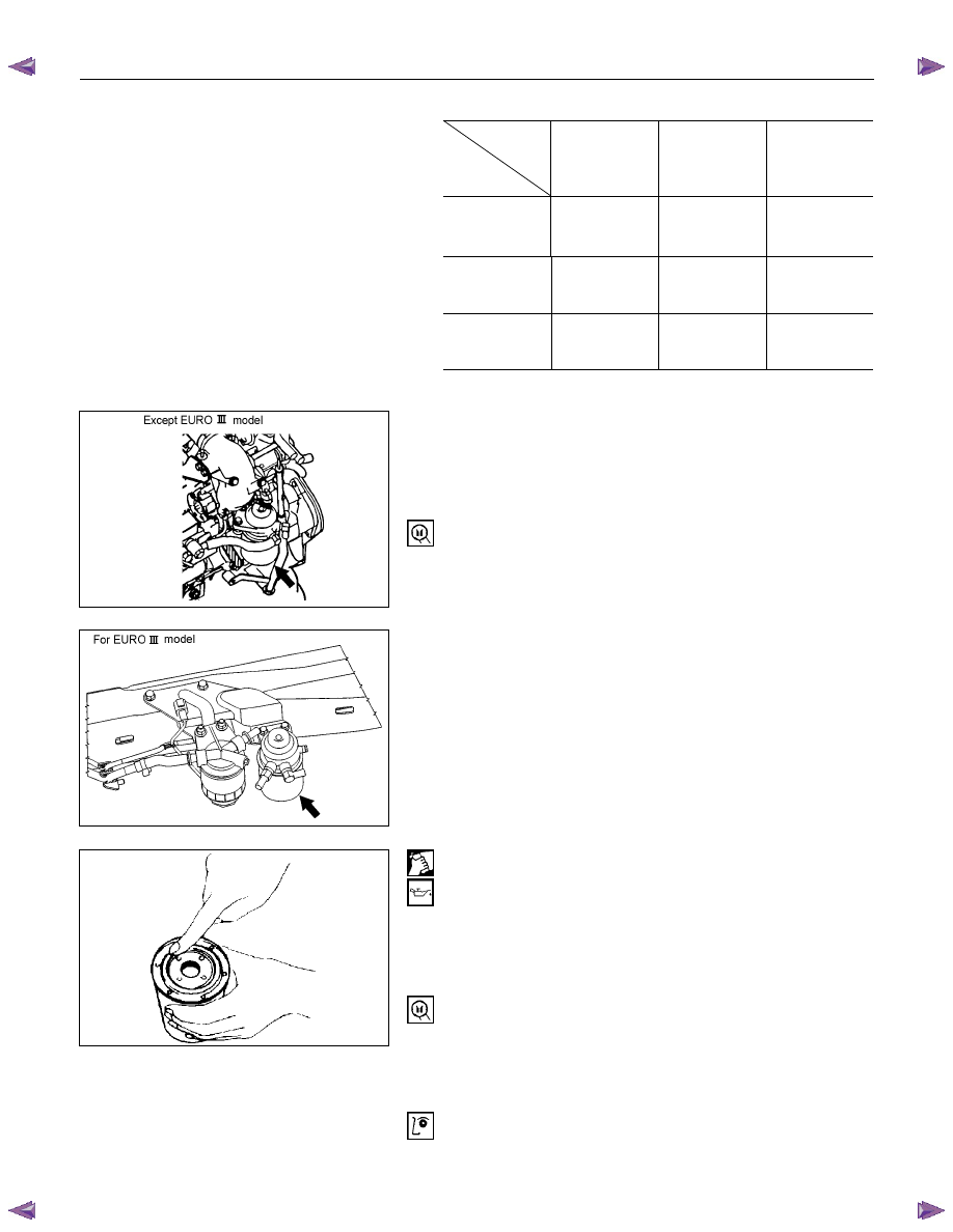
FUEL SYSTEM
Fuel Filter Replacement Procedure
1. Remove the fuel filter by turning it counterclockwise
with a filter wrench.
Filter Wrench: 5-8840-0253-0 (J-22700)
Note:
Be careful not to spill the fuel in the filter cartridge.
RTW66ASH003301
2. Clean the fuel filter cartridge fitting faces.
This will allow the new fuel filter to seat properly
3. Apply a light coat of engine oil to the O-ring.
4. Turn in the fuel filter until the sealing face comes in
contact with the O-ring.
5. Turn in the fuel filter an additional 2/3 of a turn with a
filter wrench.
Filter Wrench : 5-8840-0253-0 (J-22700)
6. Operate the priming pump until the air discharged
completely from fuel system.
7. Start the engine and check for fuel leakage.
Note:
The use of an ISUZU genuine fuel filter is strongly
recommended.
041RY00009

6A – 26 ENGINE MECHANICAL
041RY00011
Draining Procedure
The indicator light will come on when the water level in the
water separator exceeds the specified level.
Drain the water and foreign material from the water
separator (inside chassis frame) with the following
procedure.
1. Place the drain pan under the drain plug.
2. Loosen the drain plug and drain water.
3. After draining the water, tighten the drain plug.
4. Operate the priming pump on the fuel filter several
times and check for fuel leakage.
5. Check the water separator indicator light. It should be
off.
Except EURO III model
RTW46ASH002901
For EURO III model
RTW46ASH000501
Air Bleeding
1. Operate the priming pump until strong resistance is
felt.
2. Wait 1 minute, and operate the priming pump until
strong resistance is felt.
3. Once more wait, and operate the priming pump until
strong resistance is felt.
4. Turn the ignition switch to the "ON" position. Wait until
the glow indicator lamp turns off.
5. Turn the ignition switch to the "START" position and
crank the engine until it starts.
6. If the engine does not start, repeat Step 3 - 5.
7. Allow the engine to idle for 3 minutes to bleed air
completely form the fuel system and check for fuel
leakage.
Note:
Insufficient air bleeding may cause the Diagnostic
Trouble Code (DTC) store or improper engine
performance.
Нет комментариевНе стесняйтесь поделиться с нами вашим ценным мнением.
Текст