Isuzu KB P190. Manual — part 770
Engine Mechanical – V6
Page 6A1–303
Page 6A1–303
4.8 Thread
Repairs
General Information
The thread repair process involves a solid, thin walled, self-locking, carbon steel, bushing type insert. During the insert
installation process, the installation driver tool cold-rolls the bottom internal threads and expands the bottom external
threads of the insert into the base material. This action mechanically locks the insert into place.
This Section describes the recommended method of repairing threads in three specific areas of the engine.
•
general thread repair,
•
cylinder block main bearing cap bolt hole thread repair, and
•
cylinder head bolt hole thread repair.
For detailed descriptions of all thread specifications used refer to
4.9 Thread Repair Specifications
.
The drill-bit and counter-bore tool from the thread repair kit, Tool No. J-42385-700 and J-42385-2000 are designed for
use with either a suitable tap wrench or drill motor. Limited access and larger hole repair may process better using a tap
wrench. An extension from Tool J 43965 may also be required to drive the thread repair tooling dependent on access to
the hole being repaired. Use only a tap wrench when tapping the hole and during installation of the insert.
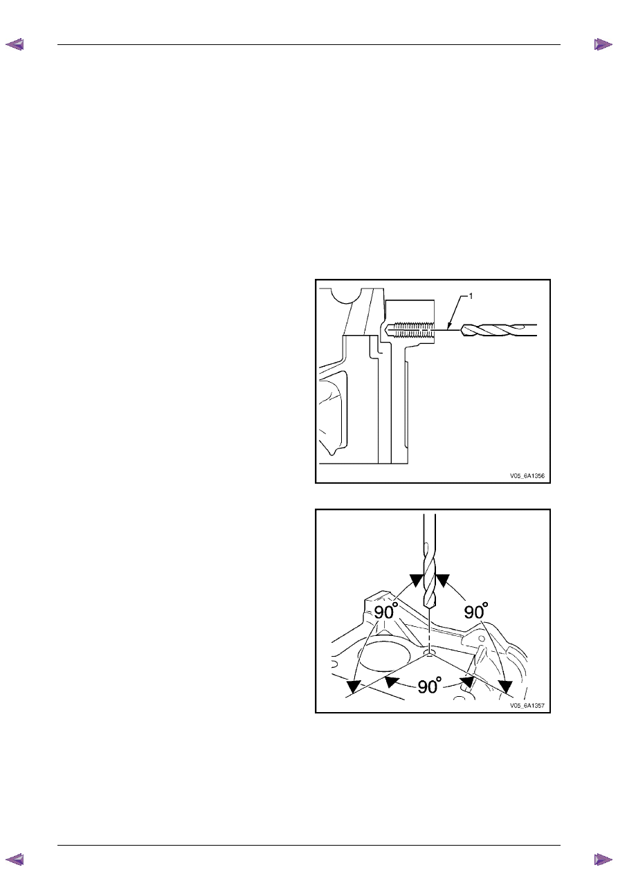
1
It is critical the drilling, counter boring and tapping of
the hole to be repaired follows the same centreline (1)
as the original hole.
Figure 6A1 – 552
2
During the drilling and tapping of the hole being
repaired, ensure the tooling is consistently machining
perpendicular to the surface of the base material.
Figure 6A1 – 553
Engine Mechanical – V6
Page 6A1–304
Page 6A1–304
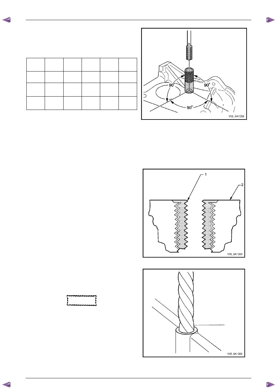
3
If the threaded hole being repaired has a base
surface perpendicular to the hole centreline, tapping
guides are available to aid in tapping the hole.
Tap
Size
Tap
Guide
Tap
Size
Tap
Guide
Tap
Size
Tap
Guide
- J
42385
- J
42385
- J
42385
6 x 1.0
729
10 x
1.5
731
14 x
1.5
736
8 x
1.25
730
12 x
1.5
732
20 x
1.5
737
Figure 6A1 – 554
General Thread Repair
N O T E
The use of a cutting type fluid such as WD 40® or
equivalent is recommended when performing the
drilling, counter boring and tapping procedures
1
When installed to the correct depth, the flange (1) of
the insert will be seated against the counter bore of
the drilled/tapped hole and just below the surface (2)
of the base material.
Figure 6A1 – 555
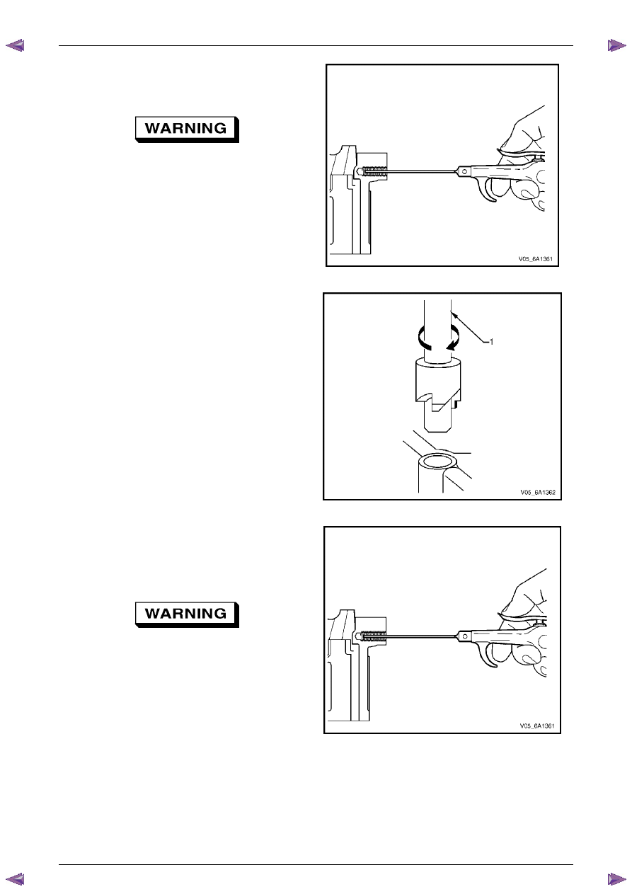
N O T E
During the drilling process, repeatedly remove
the drill and clean the swarf from the hole and
the flutes of the drill.
CAUTION
Do not drill any further than the original hole
depth.
2
Drill out the threads of the damaged hole to the
correct depth for the thread being repaired:
•
M6 inserts require a minimum drill depth of 15
mm.
•
M8 inserts require a minimum drill depth of 20
mm.
•
M10 inserts require a minimum drill depth of
23.5 mm.
Figure 6A1 – 556
Engine Mechanical – V6
Page 6A1–305
Page 6A1–305
N O T E
All swarf must be removed from the drilled hole
prior to tapping.
Safety glasses must be worn when using
compressed air.
3
Using compressed air, clean out any swarf.
Figure 6A1 – 557
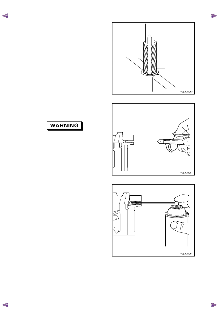
N O T E
A correctly counter bored hole will show a slight
burnishing on the surface of the base material
for 360 degrees around the drilled hole.
4
Counter bore the drilled hole to the full depth
permitted by the tool (1).
Figure 6A1 – 558
N O T E
All swarf must be removed from the drilled hole
prior to tapping.
Safety glasses must be worn when using
compressed air.
5
Using compressed air, clean out any swarf.
Figure 6A1 – 559
Engine Mechanical – V6
Page 6A1–306
Page 6A1–306
N O T E
• During the tapping process, repeatedly
remove the tap and clean the swarf from the
hole and the flutes of the tap.
• Ensure the tap has created full threads at
least to the depth equal to the insert length.
6
Using a suitable tapping wrench, tap the threads of
the drilled hole by hand only.
•
M6 inserts require a minimum drill depth of 15
mm.
•
M8 inserts require a minimum drill depth of 20
mm.
•
M10 inserts require a minimum drill depth of
23.5 mm.
Figure 6A1 – 560
N O T E
All swarf must be removed from the tapped hole
prior to insert installation.
Safety glasses must be worn when using
compressed air.
7
Using compressed air, clean out any swarf.
Figure 6A1 – 561
8
Spray a commercially available thread cleaner into
the tapped hole.
Figure 6A1 – 562
Нет комментариевНе стесняйтесь поделиться с нами вашим ценным мнением.
Текст