Isuzu KB P190. Manual — part 1474
IMMOBILIZER CONTROL SYSTEM (4JK1/4JJ1/HFV6) 11A-45
Description and Operation
Immobilizer System Description
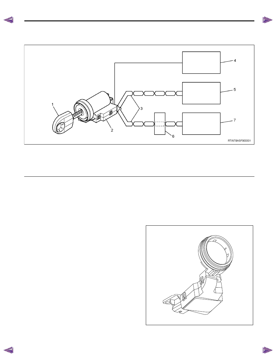
Legend
1. Transponder key
2. ICU
3. Controller area network (CAN) communication bus
lines
4. Anti-theft control unit (with anti-theft system)
5. Engine control module (ECM) (4JK1/ 4JJ1)
6. Powertrain interface module (PIM)
7. Engine control module (ECM) (HFV6)
The immobilizer controls engine starting along with the
engine control module (ECM). The main system
components are the ICU, the ECM, the PIM (HFV6)
and the transponder key. The immobilizer system is
activated (immobilized) by an incorrectly programmed
or non-programmed transponder key, the ICU or the
ECM. While this system is activated, the ECM controls
the fuel injection system and starter cut relay in order to
fail to engine running. A typical engine starting
sequence is below.
1. When the ignition switch is ON, the ICU begins
authentication of the transponder key in the
steering lock. The ICU transmits a specific request
signal to the transponder key and the transponder
key sends back a response signal to the ICU. Both
communication signals are carried out via antenna
coil.
2. Because the anti-theft system alarms if a key or
other methods unlock the door, when the
transponder key is correctly authenticated the ICU
transmits an alarm cancel (disarm) signal to the
anti-theft control unit. (With anti-theft system)
3. After the transponder key authentication is
completed, the ICU begins authentication of the
ECM. The ECM transmits a specific request signal
to the ICU and the ICU sends back a response
signal to the ECM. Both communication signals
are carried out via a controller area network (CAN)
communication bus.
4. After the ECM authentication is completed, the
ECM enables engine running.
Immobilizer System Componenet
Description
Immobilizer Control Unit (ICU)
RTW7BASH000101
11A-46 IMMOBILIZER CONTROL SYSTEM (4JK1/4JJ1/HFV6)
The ICU is installed to the steering lock. The ICU
controls the immobilizer system by authentication of the
transponder key and the ECM. An antenna coil is a part
of the ICU and it is located around steering key lock
cylinder. An antenna coil is energized when the ICU is
performing an authentication of the transponder key.
Engine Control Module (ECM)
Legend
1. ECM (4JK1/ 4JJ1)
2. ECM (HFV6)
The ECM is located inside of engine compartment via
mounting bracket and is behind air cleaner case (4JK1/
4JJ1) or attached to the engine (HFV6). The ECM
mainly controls the engine control and also exchanges
a request signal and a response signal to an ICU. If
fault occurs on immobilizer system, the ECM sets
DTC(s) and illuminates the service vehicle soon (SVS)
lamp or the malfunction indicator lamp (MIL).
Powertrain Interface Module (PIM)
The PIM is located behind the driver’s side lower hinge
pillar trim. The PIM acts as the communication gateway
between the CAN communication protocol and other
protocol. The PIM converts analog signals from some
switches into serial data. The PIM upon inputs received
from the ECM, TCM and ICU controls the operation of
instruments and indicator lamps. (HFV6)
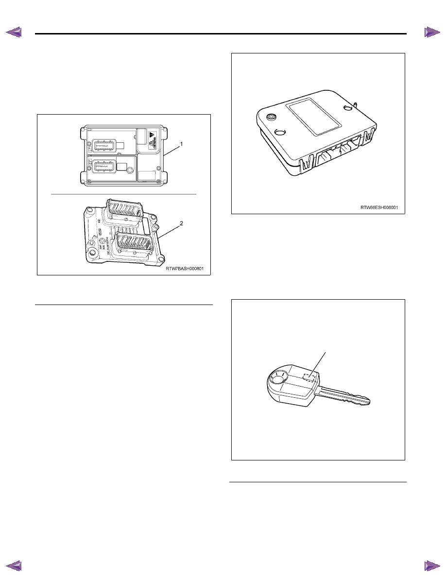
Transponder Key
Legend
1. Transponder chip
The transponder key accommodates a transponder
chip in the grip portion. The transponder keys have no
conventional power supply. The transponder chip is
energized via a radio wave supplied from an antenna
coil fitted around the steering lock cylinder. Only
transponder key that is correctly programmed key is
possible to engine run. Maximum five transponder keys
can be provided by additional programming.
RTW7BASH000201
1
IMMOBILIZER CONTROL SYSTEM (4JK1/4JJ1/HFV6) 11A-47
Special Tools and Equipment
Special Tools and Equipment
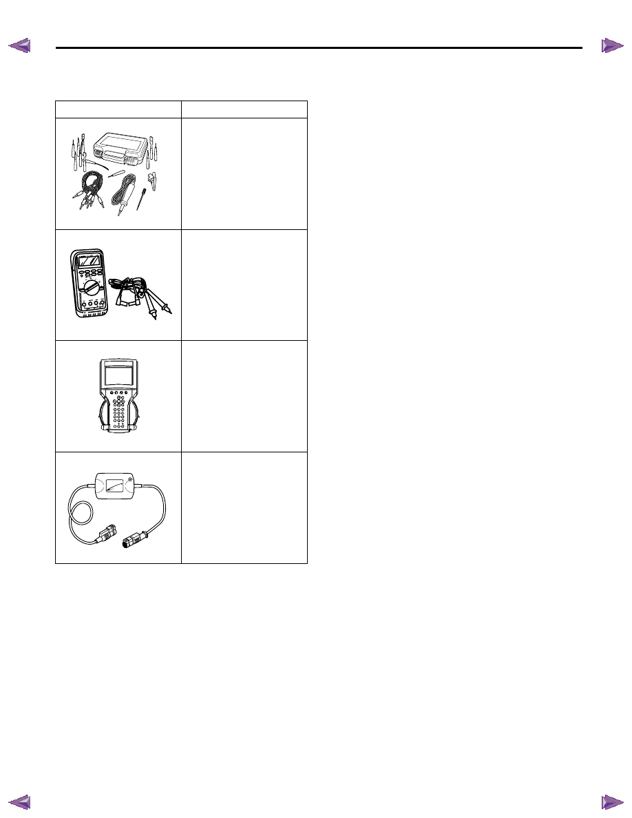
Illustration
Tool Number/ Description
5-8840-2835-0 (J-35616-C)
Connector Test Adapter Kit
(With Test Lamp)
5-8840-0285-0 (J-39200)
Digital Multimeter
Tech2 Kit
CAN-di Module
5884028350
5884002850
AAW0Z0SH015701
1851110030

IMMOBILIZER SYSTEM (C24SE, 4JA1-T) 11A-1
IMMOBILIZER SYSTEM
(C24SE, 4JA1-T)
CONTENTS
Service Precaution. . . . . . . . . . . . .. 11A-2
General Description . . . . . . . . . . . . 11A-3
What happens without proper transponder
operation? . . . . . . . . . . . . . . ... 11A-5
No proper transponder is available, what
should be done for the system? . . . . . .. 11A-5
Caution to the operation . . . . . . . . . . 11A-5
Summary of operation. . . . . . . . . . . 11A-5
What your organization should provide for
your customer . . . . . . . . . . . . . 11A-5
Car Pass . . . . . . . . . . . . . . . .. 11A-5
Security code management . . . . . . . .. 11A-5
Essential tool (Scan tool : Tech-2) . . . . .. 11A-5
Circuit Diagram . . . . . . . . . . . . .. 11A-6
Parts Location. . . . . . . . . . . . . . .. 11A-8
Immobilizer control unit (ICU); For Electronic
Control Engine (C24SE). . . . . . . . . 11A-9
Pin-outs; For Electronic Control Engine
(C24SE) . . . . . . . . . . . . . . . ...11A-10
Immobilizer control unit (ICU); Mechanical
Control Engine (4JA1-T) . . . . . . . . ...11A-11
Immobilizer coil (Antenna) . . . . . . . . . 11A-13
Transponder (Key) . . . . . . . . . . . 11A-13
Check engine lamp . . . . . . . . . . ...11A-13
Engine control module (ECM) . . . . . . ...11A-13
Car Pass Card . . . . . . . . . . . . ...11A-14
Loss of car pass card. . . . . . . . . . ..11A-14
Instructions on Filling Out the form "Data
request, car pass" . . . . . . . . . . . .11A-14
Important Instructions . . . . . . . . . . 11A-15
lmportant information on Programming . . . ..11A-17
Security code . . . . . . . . . . . . . ...11A-17
Entering a code . . . . . . . . . . . . ...11A-17
Transponder (Key) . . . . . . . . . . . .11A-17
Tech-2 Scan Tool . . . . . . . . . . . . ..11A-18
Operating Procedure . . . . . . . . . . ..11A-18
Menu . . . . . . . . . . . . . . . . . 11A-19
DTC . . . . . . . . . . . . . . . . . .. 11A-19
Clear DTC Information . . . . . . . . . .. 11A-19
Tech-2 Data Display . . . . . . . . . . .. 11A-19
Check Vehicle Identification Number (VIN) . 11A-19
Reset Immobilizer (Reset Immobilizer
Control Unit) . . . . . . . . . . . . . ... 11A-19
Reset Engine Control Module (Reset ECM) .. 11A-20
Erase transponder key . . . . . . . . . .. 11A-20
Programming Immobilizer Function . . . . 11A-21
Programming ICU . . . . . . . . . . . .. 11A-22
Programming ECM . . . . . . . . . . . 11A-23
Programming ICU and ECM . . . . . . . . 11A-24
Transponder program . . . . . . . . . . 11A-24
Data List . . . . . . . . . . . . . . . .. 11A-26
Diagnostic procedure . . . . . . . . . . . 11A-27
Clearing Diagnostic Trouble Codes . . . . . 11A-27
Verifying Vehicle Repair . . . . . . . . . ... 11A-27
Diagnostic Aids . . . . . . . . . . . . . .. 11A-27
Check the condition for system parts . . . .. 11A-27
Check the Electro-Magnetic Interference
(EMI) . . . . . . . . . . . . . . . . ... 11A-27
Check the other items . . . . . . . . . ... 11A-27
Check the operation . . . . . . . . . . ... 11A-27
Diagnostic Trouble Code (DTC) list . . . . . 11A-28
IMMOBILIZER SYSTEM CHECK . . . . . ... 11A-30
NO IMMOBILIZER WARNING LAMP . . . . 11A-32
CHECK IMMOBILIZER WARNING LAMP O
STEADY . . . . . . . . . . . . . . . . 11A-33
B0001 REPLACE ELECTRONIC CONTROL
UNIT (ECU) (IMMOBILIZER FAULT) . . . . 11A-34
B0002 IMMOBILIZER NOT PROGRAMMED ... 11A-35
B0003 TRANSPONDER KEY PROBLEM . . . 11A-36
B0004 IMMOBILIZER COIL CIRCUIT
(ANTENNA COIL FAULT) . . . . . . . . ... 11A-38
B0005 COMMUNICATION LINE W VOLTAGE
LOW . . . . . . . . . . . . . . . . . ... 11A-39
Нет комментариевНе стесняйтесь поделиться с нами вашим ценным мнением.
Текст