Isuzu KB P190. Manual — part 1370
8A-542 ELECTRICAL-BODY AND CHASSIS
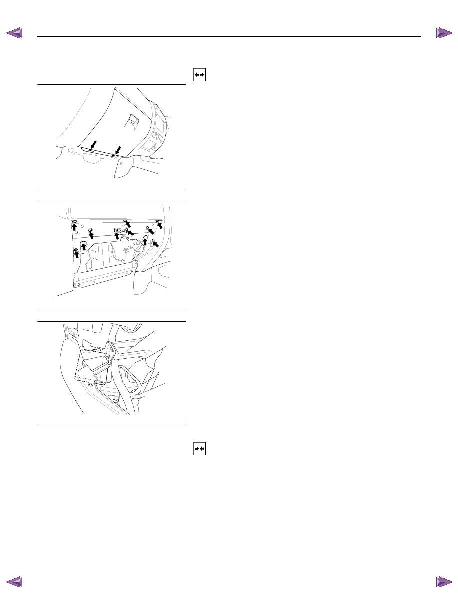
KEYLESS ENTRY CONTROL UNIT
Removal
1. Remove the glove box.
This Illustration is based on RHD
RTW580SH001601
2. Disconnect the glove box lamp connector.
This Illustration is based on RHD
RTW580SH001701
3. Remove the glove box cover.
This Illustration is based on RHD
RTW580SH001801
4. Remove the bolt of antitheft and keyless entry control unit.
5. Disconnect the keyless entry control unit connector.
6. Remove the keyless entry control unit.
Installation
Follow the removal procedure in the reverse order to install the
keyless entry control unit.
Connector
Be absolutely sure that the keyless entry control unit harness
connector is correctly installed.
This will prevent a poor contact and an open circuit.
ELECTRICAL-BODY AND CHASSIS 8A-543
RUW580SH001101
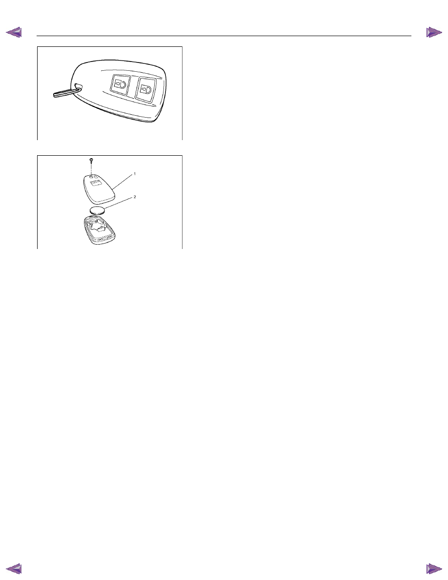
Remove Transmitter (Remote Key)
Replacing the battery in the transmitter (remote key)
Replace the battery(2) as soon as the range of the remote
control starts to become reduced.
Open the underside of the transmitter (remote key) by
removing the battery cover(1) with a screwdriver as shown in
the illustration.
Replace the battery, ensuring that it is inserted correctly.
Replace the battery cover so that it engages audibly. Make
sure that you dispose of old batteries in accordance with
environmental protection regulations.
RUW580SH003901

8A-544 ELECTRICAL-BODY AND CHASSIS
Keyless Entry System
General Description
The system’s main features are summarized as follows.
・ Keyless entry with visual feedback
・ Highly secure encrypted transmission format
incorporating rolling code strategy
・ Field programmable remote keys
・ Door lock control
・ Illuminated entry with fade out
・ Illuminated exit
・ Remote door lock / ignition key interlock
・ Door ajar warning indicator in the cluster

ELECTRICAL-BODY AND CHASSIS 8A-545
Power Door Lock System
General Description
The circuit consists of the door lock (& power window)
switch, door lock actuator for the front and rear door,
tailgate lock actuator and the door lock key switch.
The front door lock switch‐RH is always provided with
the battery voltage.
The key or the inside lock button on both driver's and
front passenger's door can activate the lock mechanism
of all the doors (including the tailgate).
When the driver's door lock switch or the front
passenger's door lock switch is turned on, current flows
for about one second to the door lock actuator of each
door connected in parallel with the front door lock (&
power window) switch‐LH to activate the actuator to
lock and unlock the doors.
Door Lock Key Switch
Removal and Installation
・ Refer to the Front Door Lock Assembly removal
and installation steps in this section.
Front Door Lock Actuator
Removal and Installation
・ Refer to the Front Door Lock Assembly removal
and installation steps in this section.
Rear Door Lock Actuator
Removal and Installation
・ Refer to the Rear Door Lock Assembly removal
and installation steps in this section.
Tailgate Lock Actuator
Removal and Installation
・ Refer to the Tailgate Lock Assembly removal and
installation steps in this section.
Нет комментариевНе стесняйтесь поделиться с нами вашим ценным мнением.
Текст