Isuzu KB P190. Manual — part 638
Engine Mechanical – V6
Page 6A1–73
7
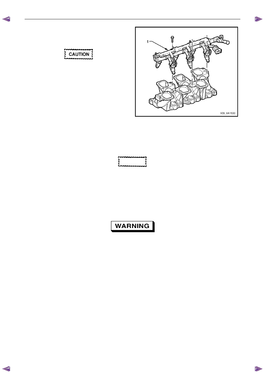
Remove the fuel rail and injector assembly. Refer to
6C1-3 Engine Management – V6 – Service
Operations.
The following precautions must be followed
when removing the fuel rail and injector
assembly:
•
Care must be taken when removing the
fuel rail and injector assembly to
prevent damage to the injector spray
tips and injector harness connector
terminals.
•
Support the fuel rail and injector
assembly after removal.
•
Plug all fuel line and manifold openings
after removal to prevent dirt and other
contaminants from entering the fuel
system.
Figure 6A1 – 53
Clean
CAUTION
Due to the aluminium alloy construction of
the intake manifold, wire brushes and steel
scrapers must not be used during the
cleaning process, as damage to sealing
surfaces may occur. Use of a wooden or
plastic scraper is preferred.
1
Clean mating surfaces ensuring any gasket material is removed.
2
Clean the manifold using a suitable solvent
Safety glasses must be worn when using
compressed air.
3
Dry the timing components with compressed air.
Inspect
1
Inspect the intake manifold for the following fault conditions:
•
Damaged sealing and mating surfaces.
•
Damaged lower intake manifold gasket.
•
Damage or excessive debris on the threaded and through holes.
•
Cracks or damage to the intake manifold body.
Engine Mechanical – V6
Page 6A1–74
N O T E
If the lower intake manifold is cracked or
damaged, it must be replaced. No welding or
patching of the intake manifold should be
performed.
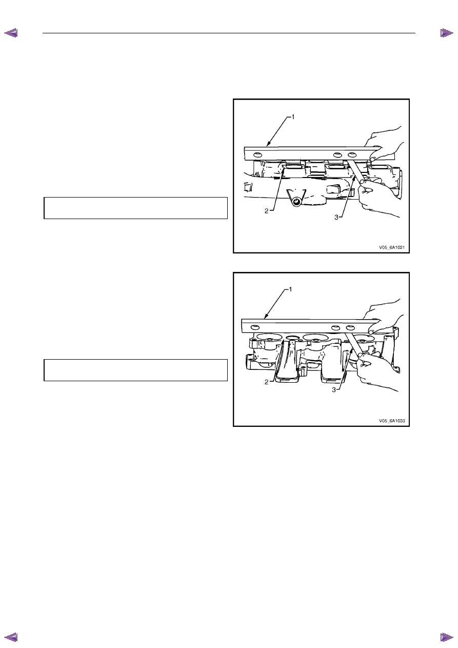
2
Place a straight edge (1) across the upper intake
manifold sealing surface (2).
3
Using a feeler gauge (3), measure the clearance
between the manifold and the straight edge.
4
If the clearance between the upper intake manifold
sealing surface and the straight edge exceeds the
specified maximum warpage, replace the manifold.
Upper manifold maximum
warpage . . . . . . . . . . . . . . . 0.05 mm
Figure 6A1 – 54
5
Place a straight edge (1) across the lower intake
manifold sealing surface (2).
6
Using a feeler gauge (3), measure the clearance
between the manifold and the straight edge.
7
If the clearance between the lower intake manifold
sealing surface and the straight edge exceeds the
specified maximum warpage, replace the manifold.
Lower manifold maximum
warpage . . . . . . . . . . . . . . . 0.05 mm
Figure 6A1 – 55
Reassemble
Reassembly of the upper to lower intake manifold is the reverse of the disassembly procedure noting the following:
1
Ensure that both the manifolds have been cleaned and inspected.
2
Ensure that the warpage of the mating surfaces is within tolerances.
3
New upper to lower intake manifold gaskets must be used.
4
Do not tighten the intake manifold to lower intake manifold attaching bolt at this stage. The intake manifold
attaching bolts must be tightened at the specified sequence during the reinstallation procedure.
Reinstall
Reinstallation of the upper intake manifold and the upper and lower intake manifold assembly is the reverse of the
removal procedure, noting the following:
1
Install the EVAP hose to the clip attached to the lower intake manifold.
2
Only new gaskets are to be fitted between the upper and lower intake manifolds.
3
If undamaged, the lower intake manifold to cylinder head gasket may be re-used, however its replacement is
strongly recommended.
Engine Mechanical – V6
Page 6A1–75
CAUTION
Tighten the intake manifold bolts in a circular
pattern starting at the centre bolt and moving
outward.
4
Ensure that all fasteners are tightened to the correct torque specification.
Upper intake manifold to lower intake
manifold attaching bolt torque specification . ...23.0 Nm
Upper intake manifold to cylinder
head attaching bolt torque specification. . . .23.0 Nm
Lower intake manifold to cylinder
head attaching bolt torque specification. . . .23.0 Nm
Fuel injector wiring harness bracket
attaching bolt torque specification. . . . . . 9.0 Nm
Incorrect wiring connector installation may
cause component malfunction or component
damage.
5
Ensure all wiring connectors are fully engaged and if applicable, locked in place.
6
Ensure all wiring harnesses are correctly routed and attached securely in their retaining clips.
7
Ensure that all hoses and pipes are routed correctly and that any retaining clips are correctly installed.
8
After installation pull on any quick connect fittings to check that each is correctly installed.
9
Start and run the engine to check for correct operation.
3.11 Exhaust Manifold Assembly
Remove
Allow the engine to cool before commencing.
Disconnection of the battery affects certain
vehicle electronic systems, refer to 1.1
WARNING, CAUTION and NOTES before
disconnecting the battery.
1
Disconnect the battery negative terminal.
Engine Mechanical – V6
Page 6A1–76
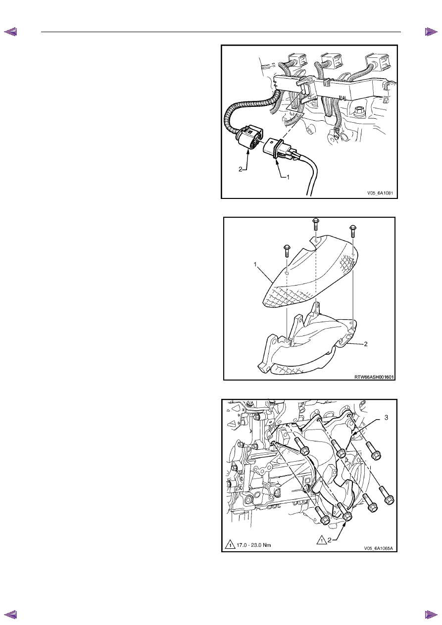
2
Remove the oxygen sensor harness connector (1)
from the retaining bracket.
3
Disconnect the oxygen sensor wiring harness
connector from the engine wiring harness connector
(2).
4
Unclip the oxygen sensor wiring harness retaining clip
and move aside.
5
For the left-hand side:
Remove the oil level indicator tube.
6
Raise the front of the vehicle and place on stands,
refer to 0A General Information.
7
Working from under the vehicle, remove the two
exhaust manifold to exhaust pipe flange nuts, refer to
6F Exhaust System - V6 - V6.
Figure 6A1 – 56
8
Remove the three bolts attaching the exhaust
manifold outer heat shield (1) to the exhaust manifold
(2).
Figure 6A1 – 57
9
Progressively loosen the seven exhaust manifold
attaching bolts (2), working from the outside to the
centre and then remove the bolts.
10
Manoeuvre the exhaust manifold (3), away from the
cylinder head.
11
Remove and discard the exhaust manifold to cylinder
head gasket.
Figure 6A1 – 58
Нет комментариевНе стесняйтесь поделиться с нами вашим ценным мнением.
Текст