Isuzu KB P190. Manual — part 514
6A-42 ENGINE MECHANICAL (C24SE)
Installation
1. Install the fastening bolts.
2. Loosen the lower alternator fastening bolt.
3. Install the alternator, power steering and V-belts.
Cylinder Head, Disassemble and Assemble
Removal
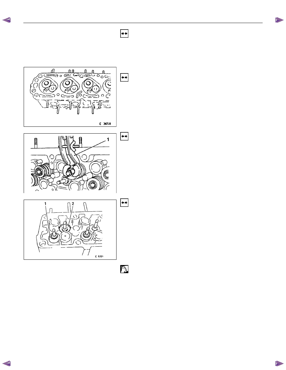
1. Remove the hydraulic valve lifters.
Lay aside in installation positions.
2. Remove the spark plugs, exhaust manifold and intake
manifold from cylinder head.
Removal
1. Mark valves.
2. Remove the tension valve springs with 5-8840-2594-0
(1).
3. Remove valve keepers, valve spring cap and valve
spring.
Removal
1. Remove the valve and valve stem seal.
2. Remove the valve spacer ring (1-exhaust) and valve
spring seat (2-intake).
3. Remove valve from cylinder head.
Clean
Sealing surfaces.
ENGINE MECHANICAL (C24SE) 6A-43
Inspection
Sealing surfaces for plane surface, guides, sliding and bearing
points for wear-see operation “Cylinder Head. Overhaul”.
Installation
1. Coat the valves with engine oil and insert in cylinder
head.
2. Install the valve spacer ring or valve rotator(exhaust) and
valve spring seal(intake).
3. Push the accompanying assembly sleeve onto valve
stem and coat with engine oil.
4. Insert a new valve stem seal with 5-8840-2601-0 (1).
5. Drive the valve stem seal carefully in to stop with light
hammer blow.
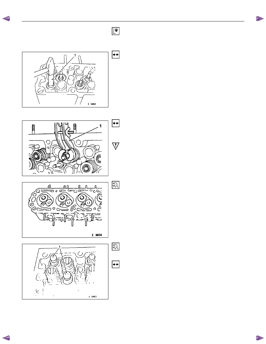
Installation
1. Install the valve springs and valve spring caps.
2. Install the tension valve springs with 5-8840-2594-0 (1),
valve keeper.
Important!
Note markings made on valves.
Tighten (Torque)
Exhaust manifold and intake manifold with new gaskets to
cylinder head.
Thermostat housing with new seal ring to cylinder head:
Tighten (Torque)
Spark plugs with spark plug wrench to cylinder head.
Installation
1. Coat hydraulic valves lifters (1) with oil.
2. Insert them in cylinder head.
Note installation position.
6A-44 ENGINE MECHANICAL (C24SE)
Valve, Grind
Valves can be reused once or twice after regrinding-only if
there are no crater-like burns on the valve cone.
Excessive grinding can cause the upper valve head edge to
become too thin.
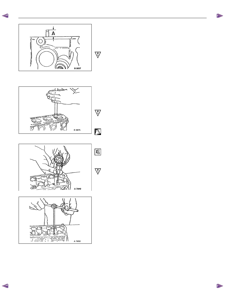
Important!
Valve stem protection must not exceed dimension “A”-use 5-
8840-2596-0.
Do not regrind valve stem ends.
For all valve reworking note that angle of valve head is 44
° and
the valve seat 45
°-see also “Technical Data”.
Valve, Grind In
Grind-In the valve to improve valve seating.
Grind-In by rhythmically lifting valves and turning uniformly.
Use commercially available grinding tool.
Important!
Use only fine-grained pastes for grinding.
Lubricate valve stem before grinding in.
Clean
After grinding, carefully clean valve and valve soat.
Valve Guide, Ream
Measure
Diameter of valve guide-dial gauge and internal measuring
instrument.
Important!
Valve oversizes are available ex-works.
Oversize identification, on the valve guide and on the valve
stem end with the following specified identificaton
flgures/letters-see also “Technical Data”.
Identification Mark
Size Production
Customer
Service
Reamer
Normal none
K
0.075 mm
1
K1
0.150mm 2
K2
Ream valve guide from the upper side of the cylinder head to
the next oversize (use 5-8840-2599-0).
After reaming, cross out identification mark and stamp in new
identification mark.
ENGINE MECHANICAL (C24SE) 6A-45
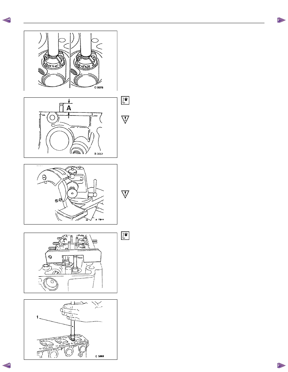
Valve Seating, Mill
Place cylinder head on block of wood.
Inlet and exhaust, Guide Drift and Valve Seat Cutter 5-8840-
2593-0.
Valve seat-45
°, side face, upper correction-30°, side face
(arrows on cutter).
Valve seat width:
Inlet-1.0 to 1.5 mm/0.04 to 0.06 in.
Exhaust-1.7 to 2.2 mm/0.072 to 0.088 in.
Inspection
Valve stem projection-use 5-8840-2596-0.
Important!
If dimension “A” is exceeded, use new valves.
Check valve stem projection again. If dimension “A” is
exceeded, replace cylinder head.
Cylinder Head, Overhaul
Cylinder head disassembled.
Valve, Grind
Important!
Ensure that there are no crater-like burns on the valve cone.
Regrinding possible once or twice.
Grinding of valve stem end is not permitted.
Angle at valve head-44
°
Inspection
Check valve stem projection as shown 5-8840-2596-0.
Valve, Grind in
Lubricate valve stem, use fine-graining grinding paste.
Lift up valve from seat rythmically using valve grinding tool (1)
for distribution of grinding paste.
Нет комментариевНе стесняйтесь поделиться с нами вашим ценным мнением.
Текст