Isuzu KB P190. Manual — part 954
Automatic Transmission – 4L60E – Electrical Diagnosis
Page 7C2–30
•
records the operating condition at the time the diagnostic fails and stores this information in the Freeze Frame/
Failure Record.
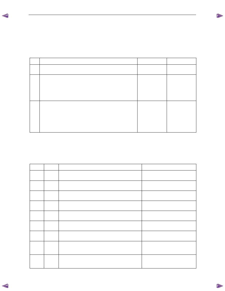
Type B – Emission Related DTCs
The TCM takes the following actions when a Type B DTC runs and fails.
•
On the first time a Type B DTC fails:
•
sets a current Type B DTC that represents the fault condition, and
•
records the operating conditions at the time the fault sets and stores this information in the Failure Records.
•
On the second consecutive ignition cycle that a Type B DTC fails:
•
illuminates the MIL, and
•
records the operating condition at the time the diagnostic fails and stores this information in the Freeze
Frame/ Failure Record.
Conditions for Clearing Type A or Type B DTCs
•
The current DTC clears when there is no fault condition in the current TCM self-diagnostics.
•
If there are no DTCs logged after six consecutive ignition cycles, the TCM deactivates the MIL.
•
Type A or Type B History DTC clears when there is no fault condition after 40 consecutive warm-up cycles.
•
Use of Tech 2 to clear DTCs.
Type C – Non-emission Related DTCs
The TCM takes the following action when a Type C DTC runs and fails:
•
sets a current Type C DTC that represents the fault condition,
•
records the operating conditions at the time the DTC is logged and stores this information in the Failure Record,
and
N O T E
The MIL does not illuminate when a Type C DTC
sets.
Conditions for Clearing Type C DTCs
•
The current DTC clears when there is no fault condition in the current TCM self-diagnostics.
•
Type C History DTC clears when there is no fault condition after 40 consecutive warm-up cycles.
•
Use of Tech 2 to clear DTCs.
Current DTCs
A DTC is a Current DTC if the fault condition that triggers the DTC is present during the last TCM self-diagnostics.
History DTCs
A DTC is a History DTC if the fault condition that triggers the DTC is not present during the last TCM self-diagnostics.
4.7
Diagnostic System Check
Description
This section procedure is organised in a logical structure that begins with the diagnostic system check. The diagnostic
system check directs you in a logical direction to the appropriate Section or diagnostic procedure.
Automatic Transmission – 4L60E – Electrical Diagnosis
Page 7C2–31
Test Description
The following numbers refer to the step numbers in the diagnostic table:
1
Within this document there are a number of requirements that must be met before you can start diagnosis. Refer to
4.2 Basic Knowledge Required, 4.3
Diagnostic Precautions and 4.4
Preliminary Checks.
2
Checks if there is data communication between Tech 2 and the TCM.
3
Checks if the TCM has set any DTCs. If no DTCs have set, the functional test must be performed, which diagnoses
the hydro-mechanical functions of the transmission.
Step Action
Yes
No
1
Have you read the Basic Diagnostic Requirements, Diagnostic
Precautions and Preliminary Checks?
Go to Step 3
Refer to Note 1
2
1
Connect Tech 2 to the DLC.
2
On Tech 2 select:
Transmission / Automatic Transmission
and follow the instruction on Tech 2.
Does Tech 2 display the TCM specifications?
Go to Step 4
Refer to 6E1
Powertrain Interface
Module
3
On Tech 2 select:
Diagnostic Trouble Codes / Read DTC Information
Does Tech 2 display any DTCs?
Go to
4.8 Diagnostic
Trouble Code List
Perform the
Functional Test,
refer to 7C3
Automatic
Transmission –
4L60E – Hydraulic
and Mechanical
Diagnosis
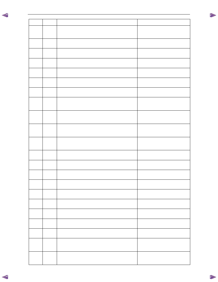
4.8
Diagnostic Trouble Code List
N O T E
If the DTC listed on Tech 2 is not contained in
this list, refer to OD Vehicle Diagnostics.
DTC Type
Description
Diagnostic
Table
P0218 C
Transmission Fluid Overtemperature
4.9
DTC P0218 – Transmission
Fluid Overtemperature
P0562 C
System Voltage Low
4.10
DTC P0562 – System
Voltage Low
P0563 C
System Voltage High
4.11
DTC P0563 – System
Voltage High
P0601 A
Transmission Control Module (TCM) Read Only Memory
(ROM)
4.12
DTC P0601 to P0604 or
P1621 – TCM Malfunction
P0602 A
Transmission Control Module (TCM) Not Programmed
4.12
DTC P0601 to P0604 or
P1621 – TCM Malfunction
P0603 A
Transmission Control Module (TCM) Random Access
Memory (RAM)
4.12
DTC P0601 to P0604 or
P1621 – TCM Malfunction
P0604 A
Transmission Control Module (TCM) Long Term Memory
Performance
4.12
DTC P0601 to P0604 or
P1621 – TCM Malfunction
P0711 C
Transmission Fluid Temperature (TFT) Sensor
Performance
4.13
DTC P0711 to P0713 –
Transmission Fluid Temperature
Sensor
P0712 C
Transmission Fluid Temperature (TFT) Sensor Circuit Low
Voltage
4.13
DTC P0711 to P0713 –
Transmission Fluid Temperature
Sensor
Automatic Transmission – 4L60E – Electrical Diagnosis
Page 7C2–32
DTC Type
Description
Diagnostic
Table
P0713 C
Transmission Fluid Temperature (TFT) Sensor Circuit High
Voltage
4.13
DTC P0711 to P0713 –
Transmission Fluid Temperature
Sensor
P0719 C
Brake Switch Circuit High Input (Stuck On)
4.14
DTC P0719 – Brake Switch
Circuit High Input (Stuck On)
P0722 B
Vehicle Speed Sensor Circuit Low Voltage
4.15
DTC P0722 – Vehicle Speed
Sensor Circuit Low Voltage
P0723 B
Vehicle Speed Sensor Circuit Intermittent
4.16
DTC P0723 – Vehicle Speed
Sensor Circuit Intermittent
P0724 C
Brake Switch Circuit Low Input (Stuck Off)
4.17
DTC P0724 – Brake Switch
Circuit Low Input (Stuck Off)
P0741 B
Torque Converter Clutch (TCC) System – Stuck Off
4.18
DTC P0741 – Torque
Converter Clutch System – Stuck Off
P0742 B
Torque Converter Clutch (TCC) System – Stuck On
4.17
DTC P0724 – Brake Switch
Circuit Low Input (Stuck Off)
P0751 B
1-2 Shift Solenoid (SS) Valve Performance – No First or
Fourth Gear
4.20
DTC P0751 – 1-2 Shift
Solenoid Valve Performance – No
First or Fourth Gear
P0752 B
1-2 Shift Solenoid (SS) Valve Performance – No Second or
Third Gear
4.21
DTC P0752 – 1-2 Shift
Solenoid Valve Performance – No
Second or Third Gear
P0756 A
2-3 Shift Solenoid (SS) Valve Performance – No First or
Second Gear
4.22
DTC P0756 – 2-3 Shift
Solenoid Valve Performance – No
First or Second Gear
P0757 A
2-3 Shift Solenoid (SS) Valve Performance - No Third or
Fourth Gear
4.23
DTC P0757 – 2-3 Shift
Solenoid Valve Performance – No
Third or Fourth Gear
P0787 A
3-2 Shift Solenoid (SS) Control Circuit Low Voltage
4.24
DTC P0787 – 3-2 Shift
Solenoid Control Circuit Low Voltage
P0788 A
3-2 Shift Solenoid (SS) Control Circuit High Voltage
4.25
DTC P0788 – 3-2 Shift
Solenoid Control Circuit High Voltage
P0894 B
Transmission Component Slipping
4.26
DTC P0894 – Transmission
Component Slipping
P0961 C
Line Pressure Control (PC) Solenoid System Performance
4.27
DTC P0961 – Line Pressure
Control Solenoid System Performance
P0973 B
1-2 Shift Solenoid (SS) Control Circuit Low Voltage
4.28
DTC P0973 – 1-2 Shift
Solenoid Control Circuit Low Voltage
P0974 B
1-2 Shift Solenoid (SS) Control Circuit High Voltage
4.29
DTC P0974 – 1-2 Shift
Solenoid Control Circuit High Voltage
P0976 A
2-3 Shift Solenoid (SS) Control Circuit Low Voltage
4.30
DTC P0976 – 2-3 Shift
Solenoid Control Circuit Low Voltage
P0977 A
2-3 Shift Solenoid (SS) Control Circuit High Voltage
4.31
DTC P0977 – 2-3 Shift
Solenoid Control Circuit High Voltage
P1621 A
Transmission Control Module (TCM) Long Term Memory
Performance
4.12
DTC P0601 to P0604 or
P1621 – TCM Malfunction
P1810 B
Transmission Fluid Pressure (TFP) Position Switch Circuit
4.32
DTC P1810, P1815 and
P1816 – Transmission Fluid Pressure
Position Switch
P1815 B
Transmission Fluid Pressure (TFP) Valve Position Switch -
Start in Wrong Range
4.32
DTC P1810, P1815 and
P1816 – Transmission Fluid Pressure
Position Switch
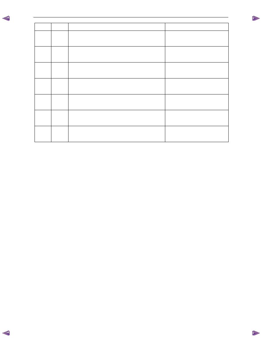
Automatic Transmission – 4L60E – Electrical Diagnosis
Page 7C2–33
DTC Type
Description
Diagnostic
Table
P1816 B
Transmission Fluid Pressure (TFP) Valve Position Switch
Indicates Park/Neutral (P/N) with Drive Ratio
4.32
DTC P1810, P1815 and
P1816 – Transmission Fluid Pressure
Position Switch
P2763 B
Torque Converter Clutch (TCC) Pressure Control (PC)
Solenoid Control Circuit High Voltage
4.33
DTC P2763 – Torque
Converter Clutch Pressure Control
Solenoid Control Circuit High Voltage
P2764 B
Torque Converter Clutch (TCC) Pressure Control (PC)
Solenoid Control Circuit Low Voltage
4.34
DTC P2764 – Torque
Converter Clutch Pressure Control
Solenoid Control Circuit Low Voltage
P2769 B
Torque Converter Clutch (TCC) Enable Solenoid Control
Circuit Low Voltage
4.35
DTC P2769 – Torque
Converter Clutch Enable Solenoid
Control Circuit Low Voltage
P2770 B
Torque Converter Clutch (TCC) Enable Solenoid Control
Circuit High Voltage
4.36
DTC P2770 – Torque
Converter Clutch Enable Solenoid
Control Circuit High Voltage
U0073 B
ECM CAN Bus Error
4.37
DTC U0073 and U0100 –
CAN-Bus No Communication With
ECM (Engine Control Module)
U0100 B
ECM CAN Bus Error
4.37
DTC U0073 and U0100 –
CAN-Bus No Communication With
ECM (Engine Control Module)
4.9
DTC P0218 – Transmission Fluid
Overtemperature
DTC Description
This diagnostic procedure supports DTC P0218 Transmission Fluid Overtemperature.
Circuit Description
The flow of transmission fluid starts in the bottom pan and is drawn through the filter, control valve body assembly,
transmission case and into the oil pump assembly. The oil pump assembly pressurises the fluid and directs it to the
pressure regulator valve where it becomes the main supply of fluid to the various components and hydraulic circuits in
the transmission. Hot fluid exiting the torque converter flows through the converter clutch apply valve and into the
transmission cooler lines, to the oil cooler located in the vehicle radiator, and auxiliary cooler if equipped. From the cooler,
fluid returns to cool and lubricate the front of the transmission. In forward drive ranges, D4 fluid from the manual valve is
routed through an orificed cup plug in the rear of the transmission case to feed the rear lube fluid circuit.
When the transmission control module (TCM) detects a high transmission fluid temperature (TFT) for a long period of
time, DTC P0218 sets. DTC P0218 is a type C DTC.
Refer to 2
Wiring Diagrams and Connector Chart to aid in diagnosis.
Conditions for Running the DTC
•
No DTCs P0711, P0712 or P0713.
•
The ignition switch is on for 5 seconds.
Conditions for Setting the DTC
The TFT is greater than 130°C for 600 seconds (10 minutes).
Action Taken When the DTC Sets
•
The TCM does not request the ECM to illuminate the MIL.
•
The TCM freezes transmission adapt functions.
Нет комментариевНе стесняйтесь поделиться с нами вашим ценным мнением.
Текст