Isuzu KB P190. Manual — part 1394
8B-4 CRUISE CONTROL SYSTEM
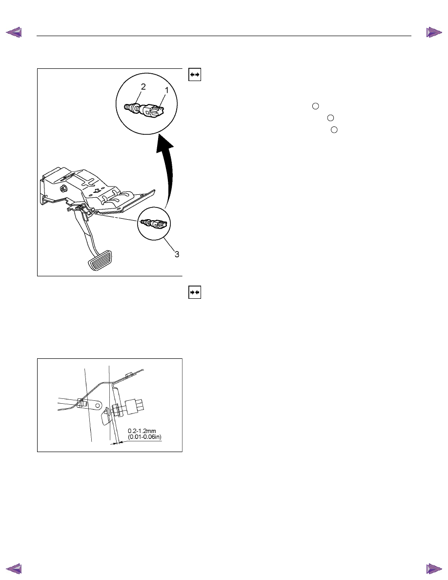
Brake Switch
RTW3A0MH000101
Removal
1. Disconnect the battery ground cable.
2. Remove the brake switch.
• Disconnect the connector
1
.
• Loosen lock nuts of the switch
2
.
• Remove the switch by turning it
3
.
Installation
To install, follow the removal procedure in reverse order, noting
the following points.
1. Check to see if the brake pedal has been returned by the
return spring to the specified position.
2. Turn the switch clock-wise until the tip of the threaded
portion of the brake switch contacts the pedal arm.
RTW780SH003201
3. Turn the switch counter-clock-wise until the space between
the tip of the threaded portion and the pedal arm is 0.2 to
1.2 mm (0.01-0.06 in) as shown in the figure.
CRUISE CONTROL SYSTEM 8B-5
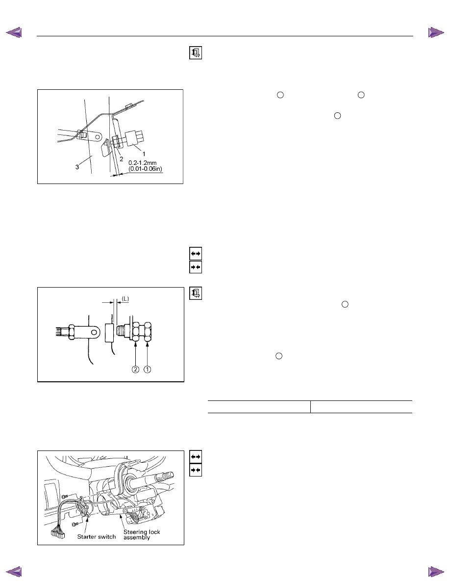
Adjustment
1. Check to be sure that the brake pedal has been completely
returned by the return spring.
2. Disconnect the switch connector.
RTW780SH003301
3. Release the lock
2
by turning the switch
1
counter-clock-
wise.
4. After doing so, pull the pedal arm
3
to you a little so that
the pedal arm is not pushed in.
5. Making the pedal arm not movable with one hand, push in
the whole switch with the other hand until the plunger of the
switch is pushed in and the switch itself hits the rubber of
the pedal arm.
In the condition, turn the switch clock-wise until "click"
sound is made and lock it.
By doing this, the switch is adjusted at 0.2 to 1.2mm (0.01-
0.06 in) clearance.
Clutch Switch
Removal and Installation
Refer to the Clutch Control removal and installation procedure
in Clutch section.
Adjustment
1. Turn the clutch switch or stopper bolt
1
until the switch bolt
or stopper bolt just touches the clutch pedal arm.
2. Adjust clutch switch or stopper bolt by backing it out half a
turn, and measure the clearance (L) between the clutch
pedal arm and the clutch switch bolt end or stopper bolt.
3. Lock the lock nut
2
.
4. Connect the clutch switch connector.
Clutch switch and clutch pedal clearance
mm (in)
Clearance 0.5-1.5
(0.020-0.059)
Starter Switch
431R300001
Removal and Installation
Refer to the Starter Switch removal and installation procedure
of Start and Charging in Body and Chassis section.
8B-6 CRUISE CONTROL SYSTEM
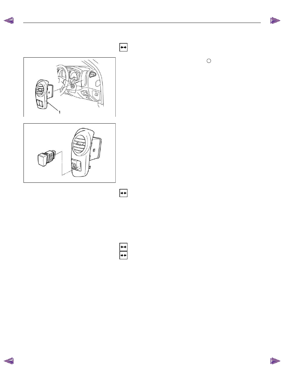
Cruise Control Main Switch
Removal
1. Disconnect the battery ground cable.
RTW78ASH001801
2. Remove the side ventilation grille
1
.
RTW78ASH002301
3. Disconnect the switch connector and push the lock from the
backside of the side ventilation grille to remove the cruise
control main switch.
Installation
To install, follow the removal procedure in reverse order, noting
the following point.
1. Push in the switch with your fingers until it locks securely.
Cruise Control Switch (Combination Switch)
Removal and Installation
Refer to the Lighting Switch (Combination Switch) removal and
installation procedure of Lighting in Body and Chassis section.

Cruise Control – HFV6
Page 8C–1
8C
Cruise Control – HFV6
A T T E N T I O N
Before performing any Service Operation or other procedure described in this Section, refer to General
Information Warnings, Cautions and Notes for correct workshop practices with regard to safety and/or
property damage.
General Information . . . . . . . . . . . . . . . . . . . . . . . . . . . . . . . ...3
WARNINGS, CAUTIONS and NOTES. . . . . . . . . . . . . . . . . . . . . . . . . . . . . 3
Definition of WARNING, CAUTION and NOTE Statements. . . . . . . . . . . . . . . . . . . . . 3
WARNING Defined. . . . . . . . . . . . . . . . . . . . . . . . . . . . . . . . . . . . 3
CAUTION Defined. . . . . . . . . . . . . . . . . . . . . . . . . . . . . . . . . . . .. 3
NOTE Defined . . . . . . . . . . . . . . . . . . . . . . . . . . . . . . . . . . . . . 4
System Components . . . . . . . . . . . . . . . . . . . . . . . . . . . . . . . . . . . . 4
Cruise Control Switch Assembly . . . . . . . . . . . . . . . . . . . . . . . . . . . . . . 5
Instrument Cluster Assembly . . . . . . . . . . . . . . . . . . . . . . . . . . . . . . . . 5
Clutch Pedal Switch (Manual Only) . . . . . . . . . . . . . . . . . . . . . . . . . . . . . 5
Stop Lamp Switch Assembly . . . . . . . . . . . . . . . . . . . . . . . . . . . . . . . .. 5
Powertrain Interface Module . . . . . . . . . . . . . . . . . . . . . . . . . . . . . . . .. 6
Engine Control Module. . . . . . . . . . . . . . . . . . . . . . . . . . . . . . . . . ... 6
Throttle Actuator Control (TAC) Assembly . . . . . . . . . . . . . . . . . . . . . . . . . . . 6
System Operation . . . . . . . . . . . . . . . . . . . . . . . . . . . . . . . . . . . . .. 6
Preliminary Information. . . . . . . . . . . . . . . . . . . . . . . . . . . . . . . . . . . 6
Enabled and Disabled . . . . . . . . . . . . . . . . . . . . . . . . . . . . . . . . . . 6
Activated and Deactivated. . . . . . . . . . . . . . . . . . . . . . . . . . . . . . . . .. 7
Enabling the Cruise Control. . . . . . . . . . . . . . . . . . . . . . . . . . . . . . . . .. 7
Brake Before Cruise . . . . . . . . . . . . . . . . . . . . . . . . . . . . . . . . . . . .. 7
Activating the Cruise Control . . . . . . . . . . . . . . . . . . . . . . . . . . . . . . . ... 7
Deactivating the Cruise Control . . . . . . . . . . . . . . . . . . . . . . . . . . . . . . ... 7
Pressing the Brake Pedal. . . . . . . . . . . . . . . . . . . . . . . . . . . . . . . . ... 7
Pressing the Cruise ON–OFF Button . . . . . . . . . . . . . . . . . . . . . . . . . . . . . 8
Rotating the Cruise Control Switch Assembly . . . . . . . . . . . . . . . . . . . . . . . . . 8
Pressing the Clutch Pedal (Manual Vehicles Only) . . . . . . . . . . . . . . . . . . . . . . . 8
Decelerating While Cruise Control is Activated . . . . . . . . . . . . . . . . . . . . . . . . .. 8
Resuming a Speed After Cruise Control Has Been Deactivated . . . . . . . . . . . . . . . . . ... 8
Accelerating While Cruise Control is Activated . . . . . . . . . . . . . . . . . . . . . . . . .. 8
Using the Cruise Control Switch Assembly . . . . . . . . . . . . . . . . . . . . . . . . . . 8
Pressing the Accelerator Pedal . . . . . . . . . . . . . . . . . . . . . . . . . . . . . . .. 8
Diagnostics . . . . . . . . . . . . . . . . . . . . . . . . . . . . . . . . . . . .9
Diagnostic General Information. . . . . . . . . . . . . . . . . . . . . . . . . . . . . . . 9
Basic Knowledge Required. . . . . . . . . . . . . . . . . . . . . . . . . . . . . . . . ... 9
Basic Diagnostic Tools Required . . . . . . . . . . . . . . . . . . . . . . . . . . . . . . . 9
Tech 2 Data List . . . . . . . . . . . . . . . . . . . . . . . . . . . . . . . . . . . . ... 10
Diagnostic Systems Check . . . . . . . . . . . . . . . . . . . . . . . . . . . . . . . . . 10
Diagnostic Systems Check . . . . . . . . . . . . . . . . . . . . . . . . . . . . . . . . . 10
Wiring Diagrams . . . . . . . . . . . . . . . . . . . . . . . . . . . . . . . . . . . . .. 12
Cruise Control Inoperative / Malfunctioning. . . . . . . . . . . . . . . . . . . . . . . . . .. 14
Circuit Description . . . . . . . . . . . . . . . . . . . . . . . . . . . . . . . . . . . 14
Manual Vehicles Only. . . . . . . . . . . . . . . . . . . . . . . . . . . . . . . . . ... 14
Test Description . . . . . . . . . . . . . . . . . . . . . . . . . . . . . . . . . . . ... 14
Diagnostic Table Notes . . . . . . . . . . . . . . . . . . . . . . . . . . . . . . . . . 14
Diagnostic Table. . . . . . . . . . . . . . . . . . . . . . . . . . . . . . . . . . . ... 14
SECTION
Нет комментариевНе стесняйтесь поделиться с нами вашим ценным мнением.
Текст