Isuzu KB P190. Manual — part 393

FUEL SYSTEM (4JK1/4JJ1) 6C-31
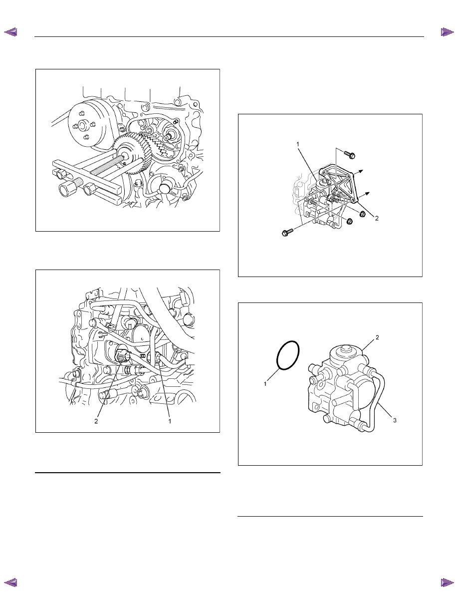
18. Remove the timing chain tension lever pivot.
19. Remove the nut and sprocket.
RTW56CSH004101
Legend
1. Tension Lever Pivot
2. Sprocket
3. Nut
20. Timing chain in moved upwards.
RTW56CSH003301
21. Paint the alignment mark.
Between idle gear A and supply pump gear.
RTW56AMH000401
6C-32 FUEL SYSTEM (4JK1/4JJ1)
22. Use a gear puller to remove the fuel supply pump
gear.
RTW56CSH002901
23. Remove the supply pump (1) and supply pump
bracket (2).
• Disconnect the connector of supply pump.
RTW58ESH002901
Legend
1. Fuel Temperature (FT) Sensor
2. Suction Control Valve (SCV)
Note:
• Do not hold the high pressure pipe, during the
supply pump removal procedure.
• Do not grasp the high pressure pipe, when
moving the supply pump from one location to
another.
RTW56CSH002001
24. Remove the supply pump and O-ring.
RTW56CSH002501
Legend
1. O-ring
2. Supply
Pump
3. High Pressure Pipe
FUEL SYSTEM (4JK1/4JJ1) 6C-33
Installation
1. Install the O-ring to the fuel supply pump.
2. Install the fuel supply pump.
Apply soapy water to the O-ring before attaching.
Note: Take care not to twist the O-ring.
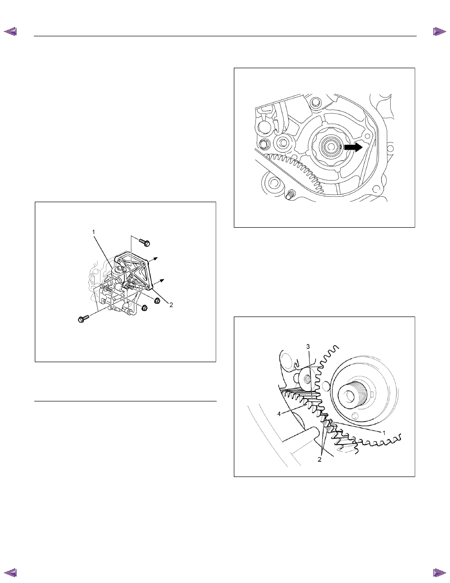
3. Install the fuel supply pump bracket.
Temporarily tighten with the bolts and nuts (Gear
case side).
Temporarily tighten with the bolts (Cylinder body
side).
Fully tighten the nuts and bolts (Gear case side).
Fully tighten the bolts (Cylinder body side).
Tightening torque: 25 N
⋅⋅⋅⋅m (2.5 kg⋅⋅⋅⋅m /18 lb ft)
RTW56CSH002001
Legend
1. Fuel Supply Pump
2. Fuel Supply Pump Bracket
4. Confirm that the supply pump camshaft key is
turned to the right and is horizontal.
RTW56CSH004301
5. Install the fuel supply pump gear to the pump
shaft.
a. Align the fuel pump gear timing mark (1) with
the idle gear A paint marks (2).
b. Ensure that the pump gear is bitten with main
gear (3) of the idle gear A. Depress the pump
gear when it is bitten with scissors gear (4) of
the idle gear A.
RTW56CSH005101
6C-34 FUEL SYSTEM (4JK1/4JJ1)
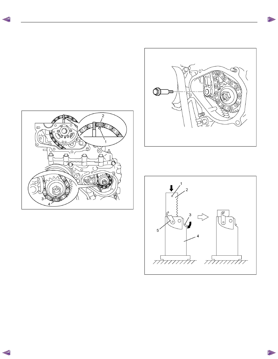
6. Install the timing chain to the each sprocket and
install the fuel supply pump sprocket to the pump
shaft.
a. Align the camshaft sprocket timing mark (1)
with the dark plate timing chain link (2).
b. Align the fuel supply pump sprocket timing
mark (3) with the yellow plate timing chain link
(4).
c. Install the fuel supply pump sprocket to the fuel
pump shaft by aligning the dowel pin that is
attached to the gear.
d. Hand-tighten the fuel supply pump shaft nut.
RTW56CSH005001
7. Install the timing chain tension lever pivot. Hand-
tighten the pivot bolt.
• Confirm the tension lever moves smoothly.
RTW56ASH019401
8. Attach the hook of the timing chain tensioner.
• Hold the latch (3) depressed. Insert the plunger
(2). Attach the hook (5) to the pin (1) to hold the
plunger in place.
RTW56CSH004401
Нет комментариевНе стесняйтесь поделиться с нами вашим ценным мнением.
Текст