Isuzu KB P190. Manual — part 653
Engine Mechanical – V6
Page 6A1–133
15
Install the secondary timing chain shoe bolt (1) and
tighten to the correct torque specification.
Secondary timing chain shoe
attaching bolt torque specification. . ...20.0 – 26.0 Nm
Figure 6A1 – 202
16
Ensure the right-hand secondary timing chain
tensioner is selected and orientated correctly.
Figure 6A1 – 203
17
Reset the right-hand secondary timing chain
tensioner.
N O T E
To reset the tensioner, use a suitably sized flat
blade screwdriver (1) or Tool No. J 45027 to
wind the plunger in a clockwise direction, into
the tensioner shaft (2).
Figure 6A1 – 204
Engine Mechanical – V6
Page 6A1–134
18
Install the tensioner shaft (1) into the right-hand
secondary timing chain tensioner body (2).
Figure 6A1 – 205
19
Compress the tensioner shaft into the body and lock
the tensioner by inserting Tool No. EN 46112 into the
access hole in the side of the tensioner body.
20
Slowly release pressure on the right-hand secondary
timing chain tensioner. The tensioner should remain
compressed.
Figure 6A1 – 206
21
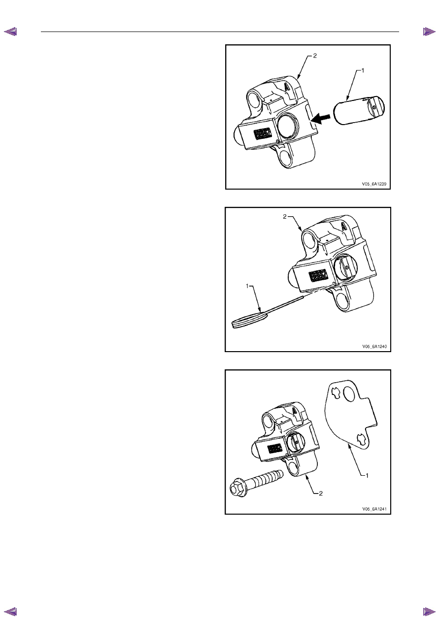
Install a new right-hand secondary timing chain
tensioner gasket (1) to the tensioner (2).
22
Install the right-hand secondary timing chain
tensioner bolts (3) through the tensioner and gasket.
23
Ensure the right-hand secondary timing chain
tensioner mounting surface on the right-hand cylinder
head does not have any burrs or defects that would
affect the sealing of the new tensioner gasket.
Figure 6A1 – 207
Engine Mechanical – V6
Page 6A1–135
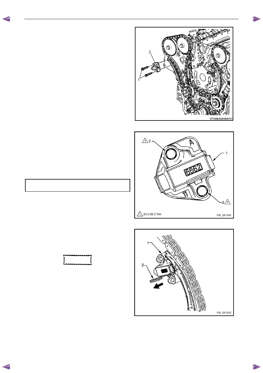
24
Place the right-hand secondary timing chain tensioner
(2) into position and loosely install the bolts (1) to the
engine block.
Figure 6A1 – 208
25
Verify the proper placement of the right-hand
secondary timing chain tensioner gasket tab (1).
26
Tighten the right-hand secondary timing chain
tensioner bolts (2) to the correct torque specification.
Secondary timing chain tensioner
attaching bolt torque specification. . ...20.0 – 26.0 Nm
Figure 6A1 – 209
27
Release the right-hand timing chain tensioner (1) by
pulling out Tool No. EN 46112 (2) and unlocking the
tensioner plunger.
CAUTION
If Tool No. EN 46112 (1) is not removed from
the tensioner body (2), the plunger will
remain in the locked position and no tension
will be placed on the timing chain, this will
cause damage to the engine.
Figure 6A1 – 210
Engine Mechanical – V6
Page 6A1–136
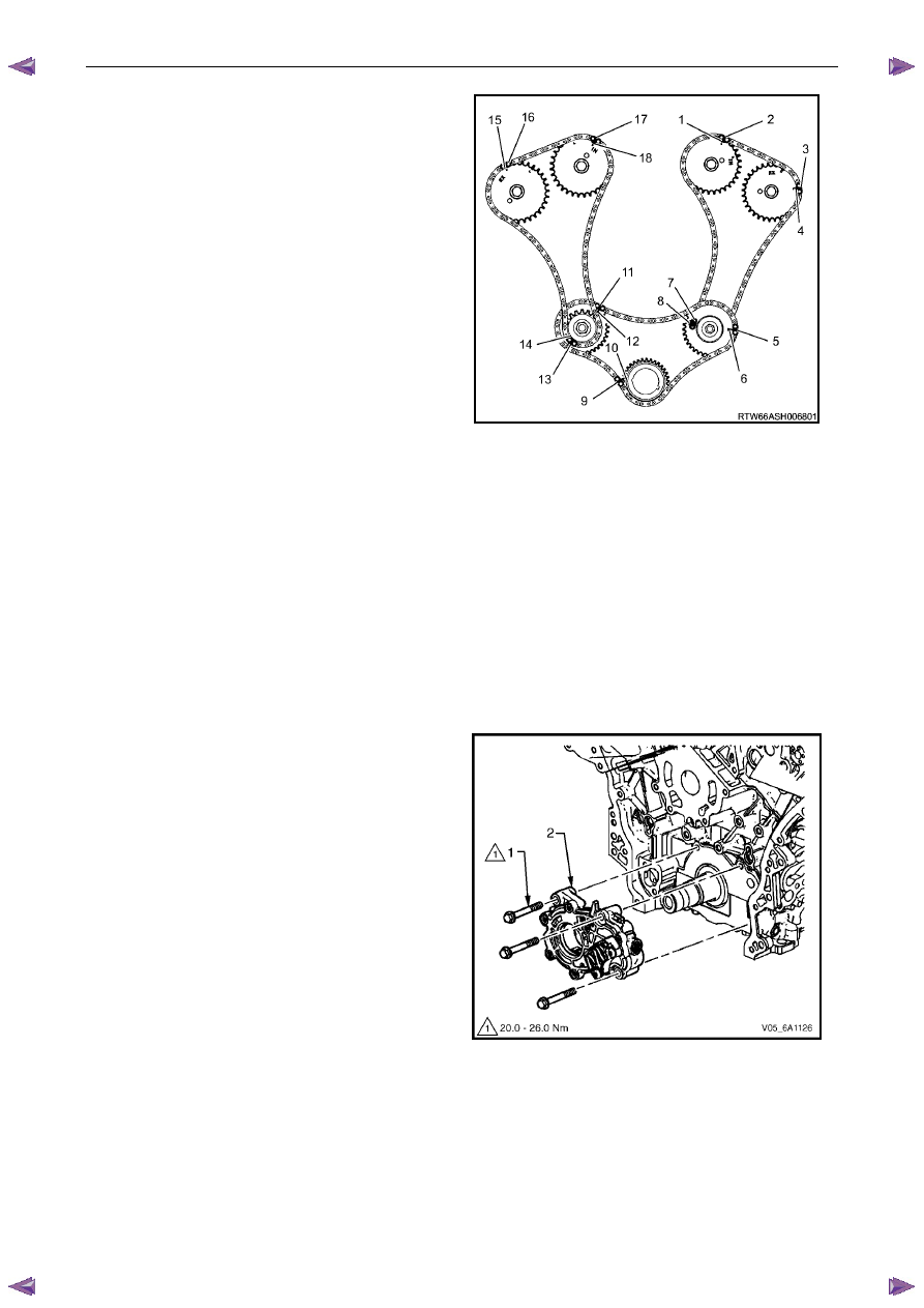
28
Verify all primary and secondary timing chain timing
mark alignments (1 to 18).
29
Remove Tool No. EN 46105 and EN 46105-2 from
the left and right-hand cylinder head camshafts.
30
Reinstall the spark plugs. Refer to 6C1-3 Engine
Management – V6 – Service Operations.
31
Reinstall the engine front cover assembly, refer to
3.15
Front Cover Assembly.
Figure 6A1 – 211
3.17 Oil Pump Assembly
Remove
N O T E
Do not remove the left-hand bank idler sprocket.
1
Remove the primary timing chain and crankshaft sprocket, refer to 3.16
Timing Chains, Tensioners, Shoes and
Guides.
2
Remove the three bolts (1) attaching the oil pump (2).
3
Remove the oil pump assembly.
Figure 6A1 – 212
Нет комментариевНе стесняйтесь поделиться с нами вашим ценным мнением.
Текст