Isuzu KB P190. Manual — part 183
BRAKES 5C-33
FRONT DISC BRAKE ASSEMBLY
REMOVAL AND INSTALLATION
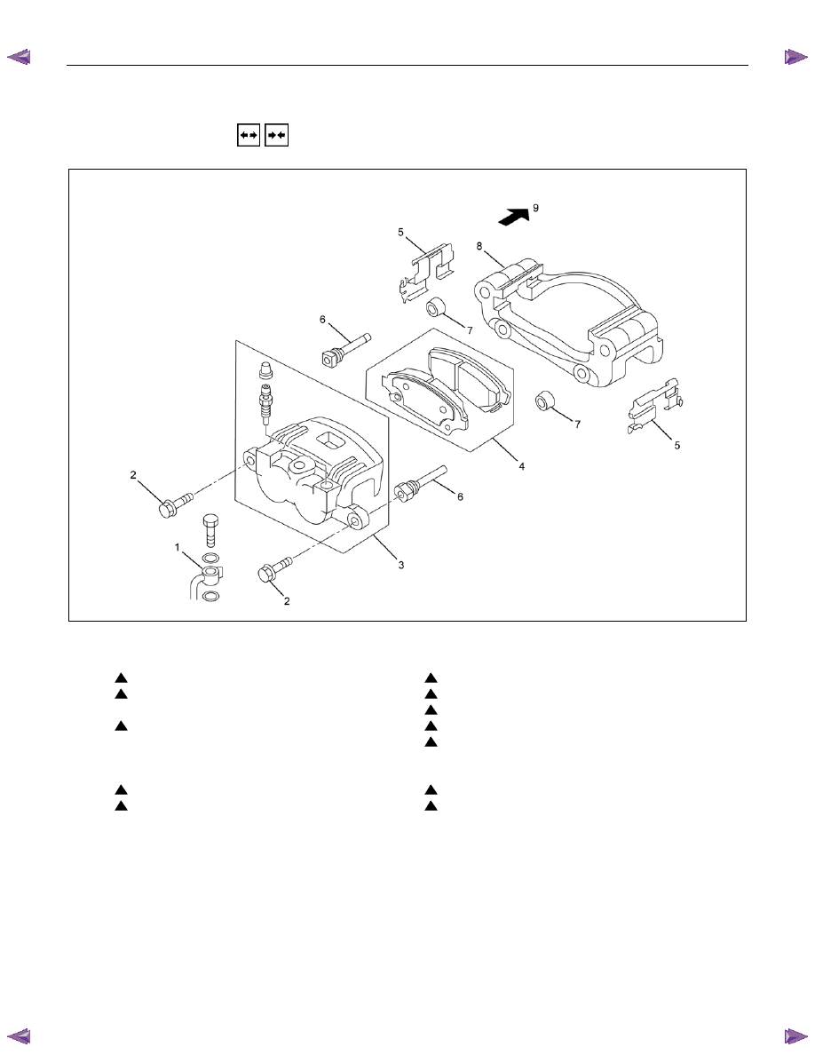
RTW55CMF000501
Removal Steps
1. Brake flexible hose
2. Lock bolt
3. Caliper assembly
4. Pad assembly with shim
5. Clip; pad
6. Slide pin
7.
Boot
8. Support bracket
9. Front hub and disc assembly
Installation Steps
9. Front hub and disc assembly
8. Support bracket
7. Boot
6. Slide pin
5. Clip; pad
4. Pad assembly with shim
3. Caliper assembly
2. Lock bolt
1. Brake flexible hose
5C-34 BRAKES
RUW55CSH000101
Important Operations - Removal
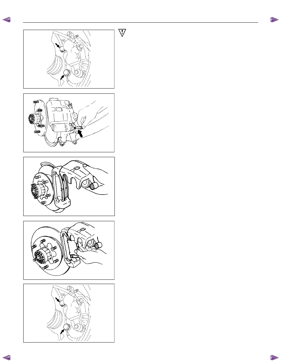
1. Brake Flexible hose
Remove the bolt and gasket and disconnect the brake flexible
hose from the caliper.
After disconnecting the flexible hose, cap or tape the openings
to prevent entry of foreign material.
RUW55CSH001501
2. Lock Bolt
Remove the lock bolt from the caliper.
4. Pad Assembly with Shim
Rotate the caliper upward.
RUW55CSH001601
Mark the lining locations if they are to be reinstalled.
RUW55CSH000101
8. Support Bracket
Take care not to damage the brake flexible hose when
removing the support bracket.
BRAKES 5C-35
9. Front Hub and Disc Assembly
For the removal procedure, refer to Section 4C “FRONT
WHEEL DRIVE”.
Important Operations - Installation
9. Front Hub and Disc Assembly
For the installation procedure, refer to the front hub and disc
reassembly procedure in Section 4C “FRONT WHEEL
DRIVE”.
RUW55CSH000101
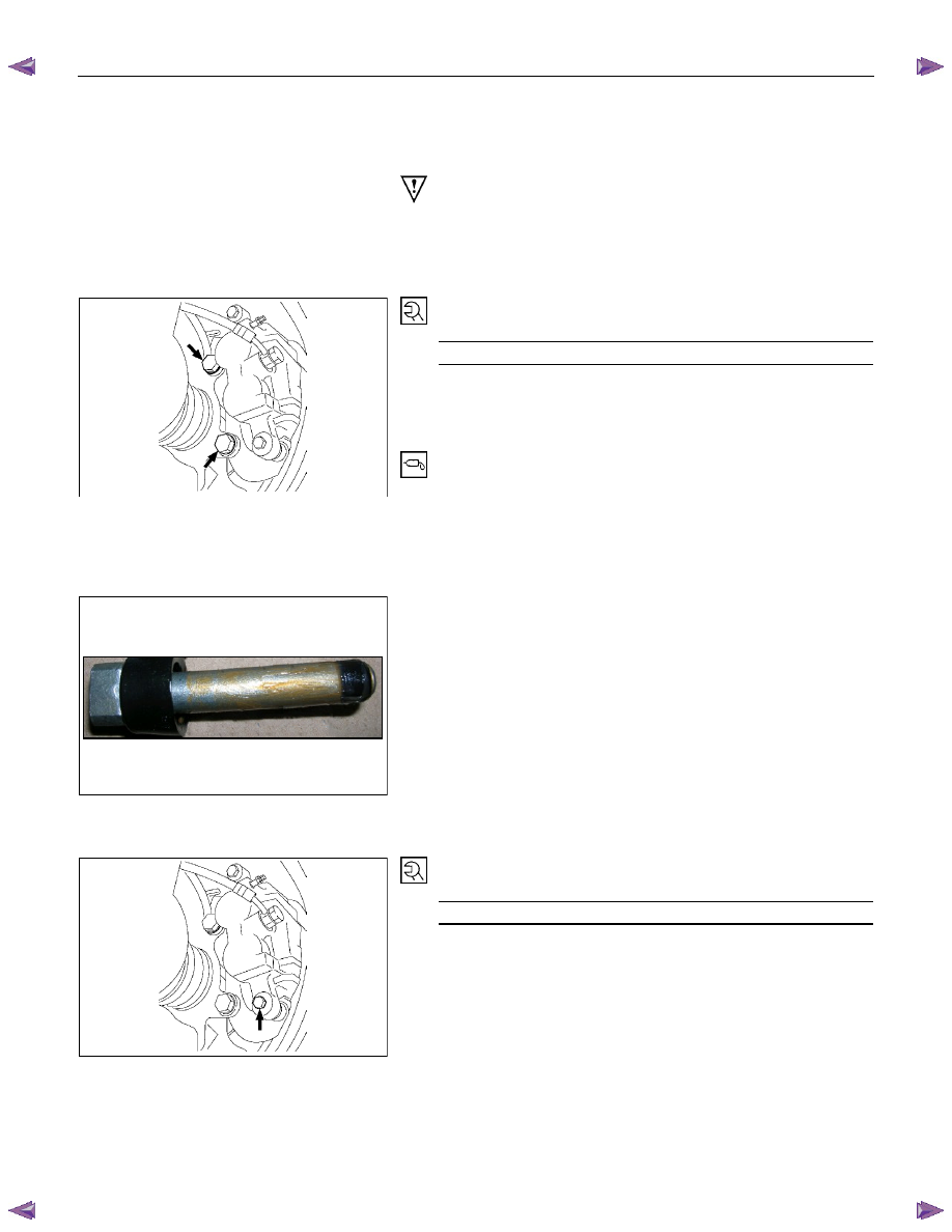
8. Support Bracket
Torque N
⋅m (kgf⋅m/lb⋅ft)
206 - 245 (21.0 – 25.0 / 152 - 181)
Set up the clip and pad before installation of the support
bracket.
7. Boot
6. Slide Pin
• Be sure to install the boots to the slide pin and the
support bracket securely.
• Apply rubber grease to the sliding surface of the slide
pin before installation of the slide pin. (Don’t use mineral
type grease.)
1) Assemble a slide pin boot to a slide pin.
2) Use 0.6g to apply grease to the slide pin entirely as
shown bellow.
3) Insert the slide pin to the housing and make sure the
boot is also inserted to the housing tightly.
5. Clip; Pad
Install new parts if necessary.
RUW55CSH000201
2. Lock Bolt
Torque N
⋅m (kgf⋅m/lb⋅ft)
32 - 40 (3.3 – 4.1 / 24 - 30)

5C-36 BRAKES
1. Brake Flexible Hose
Attach the bolt and new gasket
Torque N
⋅m (kgf⋅m/lb⋅ft)
29 -39 (3.0 - 4.0 / 22 - 29)
After installation, the bleeding and replenishing procedure must
be performed.
Wipe the circumference of the hose clean.
Note:
•••• Always use new gaskets.
• Be sure to put the hooked edge of the flexible hose end
into the anti-rotation cavity.
Нет комментариевНе стесняйтесь поделиться с нами вашим ценным мнением.
Текст