Isuzu KB P190. Manual — part 1417
SUPPLEMENTAL RESTRAINT SYSTEM 9A-33
Inspections Required After An Accident
CAUTION: Certain SRS components must be
replaced after a frontal crash involving air bag
deployment.
In all types of accidents regardless of “Air Bag”
deployment, visually inspect all of the following
components and replace as required:
– Driver air bag assembly
– Passenger air bag assembly
– Steering
wheel
– SRS coil assembly
– Steering
column
– Knee bolster and instrument panel mounting
attachments
– Driver seat and belt
– Passenger seat and belt
– SRS control unit
The SRS control unit should always be checked
according to “SRS Control Unit Replacement
Guidelines.”
CAUTION: Refer to “SRS control unit Replacement
Guidelines” below for important information on
SRS control unit replacement in both deployment
and non–deployment crashes.
Inspect the SRS coil assembly wiring and the steering
wheel for any sign of scorching, melting, or damage
due to excessive heat. If the coil assembly wire or
steering wheel is damaged, replace them. The
steering column and wheel must be dimensionally
checked to determine if they are damaged. Refer to
“steering wheel” in this manual.
Never use SRS parts from another vehicle. This does
not include remanufactured parts purchased from an
authorized ISUZU/GM Retailer; they may be used for
SRS repairs.
Do not attempt to repair the SRS control unit, the SRS
harness, the SRS coil assembly, the air bag assembly,
the steering wheel, or the steering column. Service of
these items is replacement only. Verify replacement
part numbers.
CAUTION: Proper operation of the SRS control
unit and the supplemental restraint system (SRS)
requires that any repairs to the vehicle structure
return it to its original production configuration.
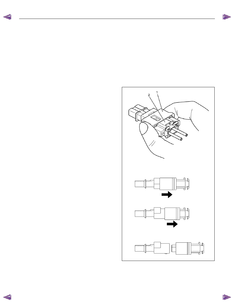
SRS Connectors
CAUTION: The special yellow color connectors are
used for the supplemental restraint system-air bag
circuit. When removing the cable harness, do not
pull the cables otherwise cable disconnection may
occur. When connecting the SRS connector, insert
the connector completely. Imperfect locking may
cause malfunction of the SRS circuit.
Removal
To remove the connector, hold the cover insulator (1)
and pull it. The cover insulator slides and the lock will
be released. Do not hold the socket insulator (2).
827RW028
9A-34 SUPPLEMENTAL RESTRAINT SYSTEM
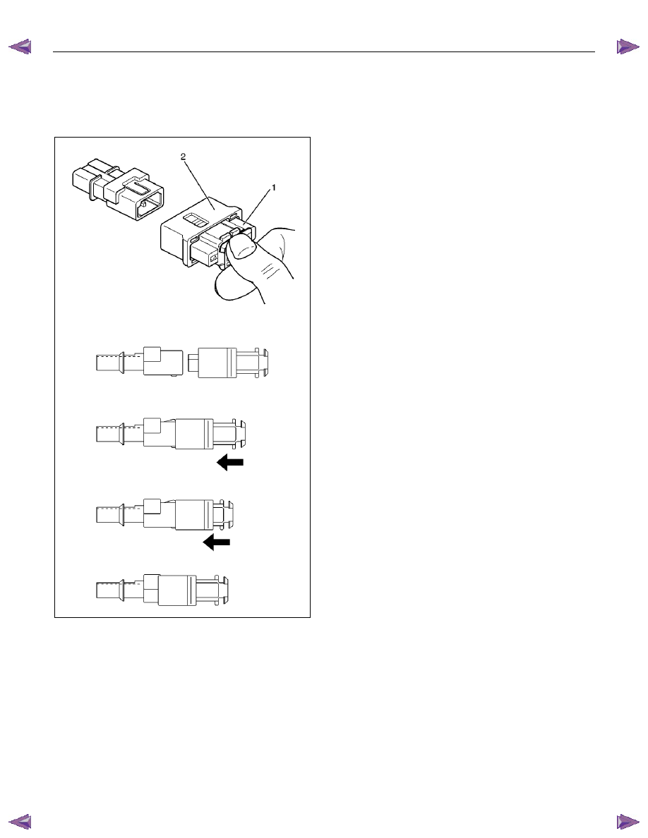
Installation
To install the connector, hold the socket insulator (1)
and insert it. The cover insulator slides and the
connector will be locked. Do not hold the cover
insulator (2).
827RW027
SUPPLEMENTAL RESTRAINT SYSTEM 9A-35
SRS Control Unit
Service Precautions
WARNING: DURING SERVICE PROCEDURES, BE
VERY CAREFUL WHEN HANDLING THE SRS
CONTROL UNIT. NEVER STRIKE OR JAR THE SRS
CONTROL UNIT. UNDER SOME
CIRCUMSTANCES, IT COULD CAUSE
DEPLOYMENT AND RESULT IN PERSONAL
INJURY OR IMPROPER OPERATION OF THE
SUPPLEMENTAL RESTRAINT SYSTEM (SRS).
THE SRS CONTROL UNIT MOUNTING BRACKET
BOLTS MUST BE CAREFULLY TORQUED TO
ASSURE PROPER OPERATION. NEVER POWER
UP THE SRS WHEN THE SRS CONTROL UNIT IS
NOT RIGIDLY ATTACHED TO THE VEHICLE. THE
SRS CONTROL UNIT COULD BE ACTIVATED
WHEN POWERED WHILE NOT RIGIDLY
ATTACHED TO THE VEHICLE WHICH COULD
CAUSE DEPLOYMENT AND RESULT IN
PERSONAL INJURY.
WARNING: PROPER OPERATION OF THE SRS
CONTROL UNIT REQUIRES THE SRS CONTROL
UNIT TO BE RIGIDLY ATTACHED TO THE
VEHICLE STRUCTURE AND THAT THE ARROW
ON THE SENSOR BE POINTING TOWARD THE
FRONT OF THE VEHICLE.
The SRS control unit is specifically calibrated and is
keyed to the SRS control unit location SRS wiring
harness. Caution should be used to ensure proper
location of the SRS control unit. The keying of the
SRS control unit to its location and wiring harness
connectors should never be modified in the field.
Removal
1. Disable the SRS (Refer to “Disabling the SRS” in
this section).
2. Remove the transmission knob (for M/T) and
transfer lever knob.
3.
Remove the front console assembly and
disconnect the wiring harness connector.
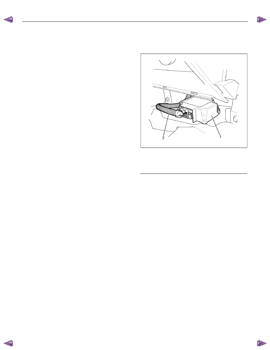
4.
Disconnect the SRS control unit harness
connector.
5. Remove the three nuts which are fixing the SRS
control unit.
And remove the SRS control unit.
RTW79ASH000401
Legend
(1) SRS control unit
(2) SRS Harness
Installation
1. Install the SRS control unit on the bracket and
fixing nuts and tighten the fixing nuts to the
specified torque.
Torque: 7
±±±± 2 N⋅⋅⋅⋅m (0.7 ±±±± 0.2 kgf⋅⋅⋅⋅m/61 lb in)
2. Connect the SRS control unit harness connector.
3. Install the front console.
4. Install the transmission knob (for M/T) and transfer
lever knob.

9A-36 SUPPLEMENTAL RESTRAINT SYSTEM
5. Enable the SRS. (Refer to “Enabling the SRS” in
this section)
RTW79ASH000401
Legend
(1) SRS control unit
(2) SRS Harness
Нет комментариевНе стесняйтесь поделиться с нами вашим ценным мнением.
Текст