Isuzu KB P190. Manual — part 977

Automatic Transmission – 4L60E – Electrical Diagnosis
Page 7C2–122
Action Taken When the DTC Sets
•
The TCM requests the ECM to illuminate the MIL during the second consecutive trip in which the conditions for
setting the DTC are met.
•
The TCM commands maximum line pressure.
•
The TCM freezes transmission adaptive functions.
•
The TCM inhibits TCC engagement.
•
At the time of the first failure, the TCM records the operating conditions when the conditions for setting the DTC are
met. The TCM stores this information as a Failure Record.
•
At the time of the second failure, the ECM records the operating conditions when the conditions for setting the DTC
are met. The ECM stores this information as a Freeze Frame.
•
The TCM stores either DTC U0073 or DTC U0100 in TCM history during the second consecutive trip in which the
conditions for setting the DTC are met.
Conditions for Clearing the DTC
•
The ECM turns off the MIL after the fourth consecutive drive trip in which the TCM does not send a MIL illumination
request.
•
Tech 2 can clear the DTC.
•
The TCM clears the DTC from TCM history if the vehicle completes 40 warm-up cycles without a non-emission
related diagnostic fault occurring.
•
The TCM cancels the DTC default actions when the ignition is off long enough to power down the TCM.
Test Description
The following number refers to the step numbers in the diagnostic table:
1
The following tests are included in the Diagnostic System Check.
•
Tests the integrity of the GM LAN serial data communication circuit.
•
Tests for fault conditions on the vehicle immobiliser system stored in the ICU.
DTC P0864 and U0101 Diagnostic Table
Step Action
Yes
No
1
Has the Diagnostic System Check been performed?
Go to Step 2
Refer to
4.7 Diagnostic
System Check

Automatic Transmission – 4L60E – Electrical Diagnosis
Page 7C2–123
Step Action
Yes
No
2
1
Connect Tech 2 to the DLC.
2
Turn on the ignition, with the engine off.
N O T E
Before clearing the DTC, use the Tech
2 Freeze
Frame/Failure Record to record the transmission
parameters at the time the DTC set. Using Tech 2 to clear
the DTC(s) erases the Freeze Frame/Failure Record
records from the TCM.
3
On Tech 2 select:
Transmission / Automatic Transmission / Diagnostic
Trouble Codes / Freeze Frame.
4
Select the relevant DTC and note the parameters at the time of
the DTC setting.
5
On Tech 2 select:
Diagnostic Trouble Codes / Clear Engine & Transmission
DTCs.
6
Follow the instructions on Tech 2 and clear the DTCs.
7
Operate the vehicle within the conditions for running the DTC.
8
On Tech 2 select:
Diagnostic Trouble Codes / Read DTC Information.
Has either DTC PU0073 or DTC U0100 set?
Go to Step 3
Check for an
intermittent fault in
the circuit, refer to
8A Electrical-Body
and Chassis
3
Using Tech 2, attempt to communicate with the PIM.
Does the PIM failed to communicate?
Refer to the 6E1
Powertrain Interface
Module – V6
Go to Step 4
4
Are DTCs also set in the PIM?
Refer to 6E1
Powertrain Interface
Module – V6
Go to Step 5
5
Replace the TCM, refer to 7C4 Automatic Transmission – 4L60E –
On-vehicle Servicing.
Was the repair completed?
Go to Step 6
—
6
1
Using Tech 2, clear the DTCs.
2
Switch off the ignition for 30 seconds.
3
Start the engine.
4
Operate the vehicle within the conditions for running the DTC.
Does any of the serial data communication circuit – TCM DTCs fail
this ignition cycle?
Go to Step 2
Go to Step 78
7
Using Tech 2, select the DTC display function.
Does Tech 2 display any DTCs?
Go to the
appropriate DTC
Table
System OK
When all diagnosis and repairs are completed, check the system for correct operation.
Automatic Transmission – 4L60E – Electrical Diagnosis
Page 7C2–124
5 Electrical
Specifications
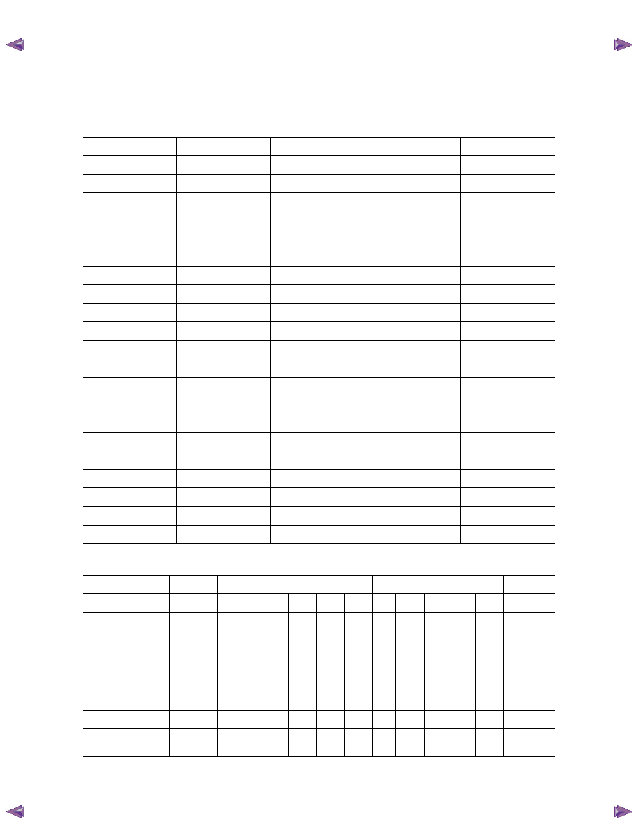
5.1
Transmission Fluid Temperature (TFT)
Sensor Specifications
Temperature
Minimum Resistance
Normal Resistance
Maximum Resistance
Signal
°C
Ω
Ω
Ω Volts
-40 90636
100707
110778 5.00
-30 47416
52684
57952 4.78
-20 25809
28677
31545 4.34
-10 14558
16176
17794 3.89
0 8481
9423
10365
3.45
10 5104 5671 6238 3.01
20 3164 3515 3867 2.56
30 2013 2237 2461 1.80
40 1313 1459 1605 1.10
50 876 973
1070
3.25
60 600 667 734 2.88
70 420 467 514 2.56
80 299 332 365 2.24
90 217 241 265 1.70
100 159 177 195 1.42
110 119 132 145 1.15
120 89.9 99.9 109.9 0.87
130 69.1 76.8 84.5 0.60
140 53.8 59.8 65.8 0.32
150 42.5 47.2 51.9 0.00
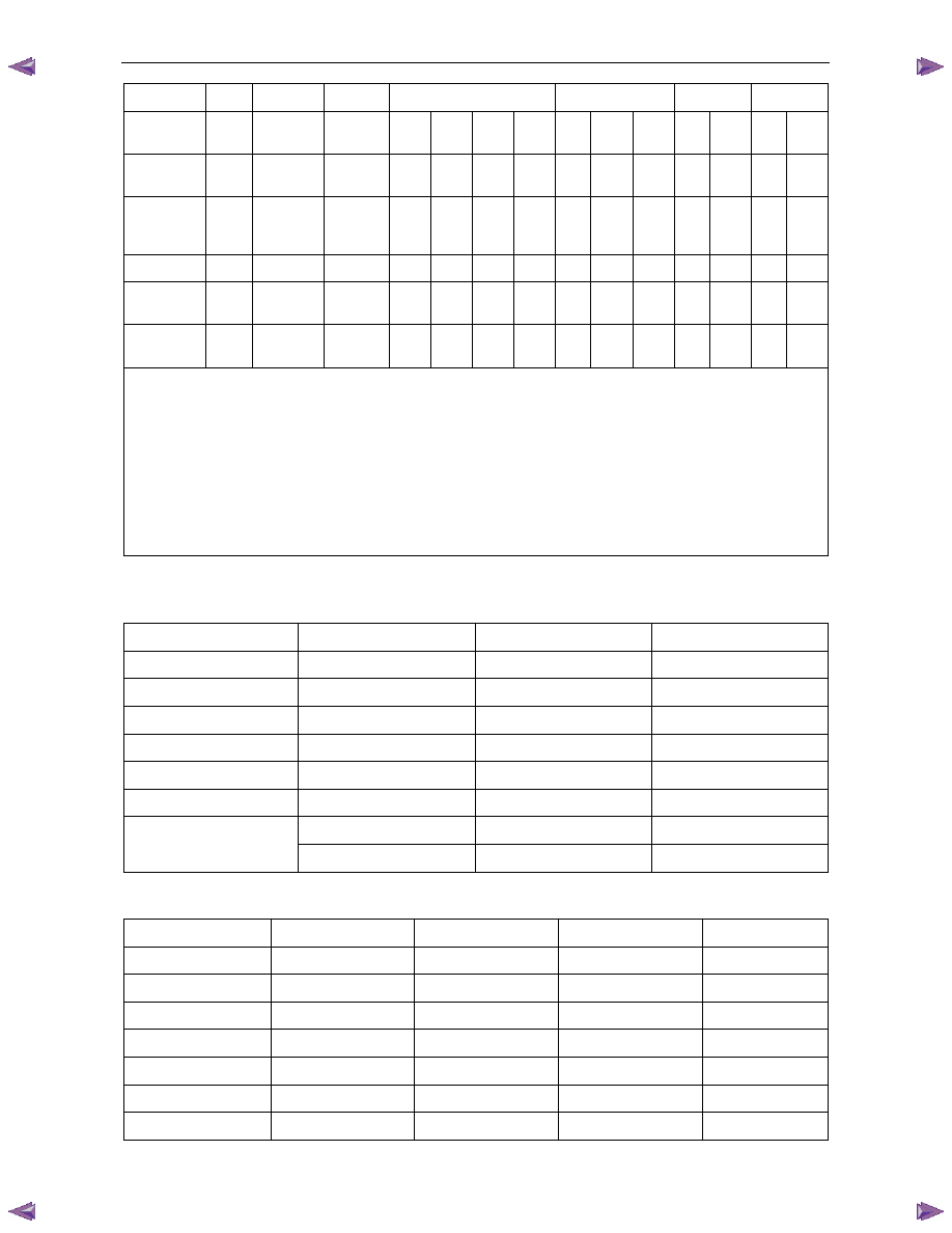
5.2 Range
Reference
Range Park
Reverse
Neutral
4
3
2
1
Gear
1
st
2
nd
3
rd
4
th
1
st
2
nd
3
rd
1
st
**
2
nd
1
st
2
nd
***
Shift
Solenoid A
(1-2 Shift
Solenoid)
ON*
ON*
ON*
ON
OFF
OFF
ON
ON
OFF
OFF
ON OFF ON
OFF
Shift
Solenoid B
(2-3 Shift
Solenoid)
ON*
ON*
ON*
ON
ON
OFF
OFF
ON
ON
OFF
ON ON ON
ON
2-4
Band -
-
-
- A - A - A - - A - A
Reverse
Input Clutch
-
A
-
- - - - - - - - - - -
Automatic Transmission – 4L60E – Electrical Diagnosis
Page 7C2–125
Range Park
Reverse
Neutral
4
3
2
1
Overrun
Clutch
-
-
-
- A A - - A A A A A
A
Forward
Clutch
-
-
-
A A A A A
A A A A A
A
Forward
Sprag Clutch
Assembly
-
-
-
H H H - H
H H H H H
H
3-4
Clutch -
-
-
- - A A - - A - - - -
Lo/Roller
Clutch
-
-
-
H - - - H
- - H - H
-
Lo/Rev
Clutch
A
A
-
- - - - - - - - - A
-
A = Applied
H = Holding
ON = Solenoid is energised
OFF = Solenoid is de-energised
* Shift solenoid state is a function of the vehicles speed and may change if the vehicle speed increases sufficiently
** Manual shift from second to first gear is electronically prevented under normal operating conditions
*** Manual shift from first to second gear is only available above approximately 48 – 56 km/h
5.3
Transmission Fluid Pressure Manual
Valve Position Switch Logic
Gear Selector Position
Signal A
Signal B
Signal C
Park/Neutral
Open 12 V
Closed 0 V
Open 12 V
Reverse
Closed 0 V
Closed 0 V
Open 12 V
Drive 4
Open 12 V
Closed 0 V
Closed 0 V
Drive 3
Open 12 V
Open 12 V
Closed 0 V
Drive 2
Open 12 V
Open 12 V
Open 12 V
Drive 1
Closed 0 V
Open 12 V
Open 12 V
Closed 0 V
Open 12 V
Closed 0 V
Invalid
Closed 0 V
Closed 0 V
Closed 0 V
5.4
Transmission Range Switch Logic
Gear Selector Position
Signal A
Signal B
Signal C
Signal P
Park (P)
Closed 0 V
Open 12 V
Open 12 V
Closed 0 V
Reverse (R)
Closed 0 V
Closed 0 V
Open 12 V
Open 12 V
Neutral (N)
Open 12 V
Closed 0 V
Open 12 V
Closed 0 V
Drive 4 (OD)
Open 12 V
Closed 0 V
Closed 0 V
Open 12 V
Drive 3 (3)
Closed 0 V
Closed 0 V
Closed 0 V
Closed 0 V
Drive 2 (2)
Closed 0 V
Open 12 V
Closed 0 V
Open 12 V
Drive 1 (1)
Open 12 V
Open 12 V
Closed 0 V
Closed 0 V
Нет комментариевНе стесняйтесь поделиться с нами вашим ценным мнением.
Текст