Isuzu KB P190. Manual — part 180
BRAKES 5C-21
LOAD SENSING PROPORTIONING VALVE (LSPV)
RTW35CMF000101
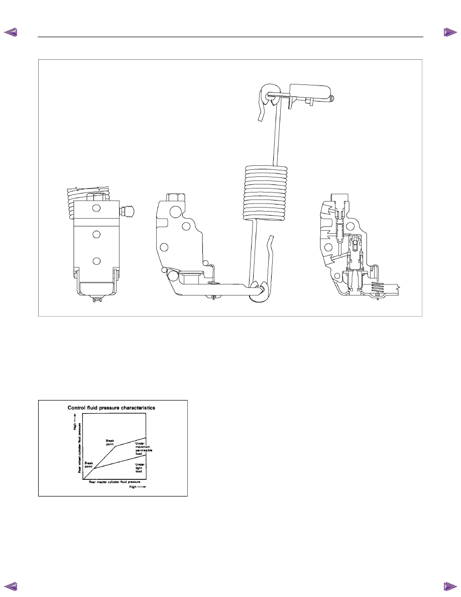
Structure and Operation
The following is an explanation of the structure and operation
of the spring type load sensing device.
This device controls the fluid pressure to the rear brakes in
accordance with changes in rear axle load (vertical
displacements of the rear axle springs).
•••• Structure
This device consists of a load sensing spring and a valve.
The valve is mounted through a bracket to the frame.
One end of the load sensing spring is fixed to the valve at
the frame and the other end to the rear axle housing
through a bracket.
5C-22 BRAKES
RTW35CSH001001
•••• Operation
1) Outline
When the LSPV (Load Sensing Proportioning Valve)
detects a change in load weight, the load sensing spring
stretches.
Its reaction force is transmitted to the bottom of the load
sensing valve to secure an optimum rear wheel cylinder
fluid pressure break point in proportion to the actual load
weight.
Besides, if the front brake system should fail, the device is
designed to prevent the master cylinder fluid pressure from
decreasing and to apply it directly to the rear wheel cylinder
to obtain a sufficient braking performance.
RTW35CSH001101
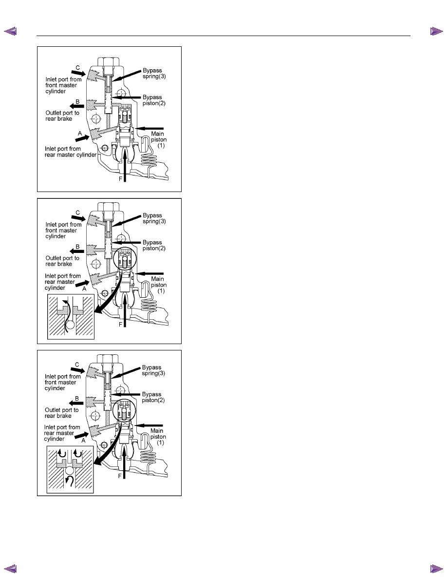
2) Bellow cutting point.
The Force (F) keeps the main piston (1) the rest position.
The inlet pressure (A) and outlet pressure (B) are the same
as well as the inlet pressure (C) from front master cylinder.
The bypass piston (2) is kept on rest position by equilibrium
of the pressures (A) and (C) and the bypass spring load (3).
RTW35CSH001201
3) Cutting point.
The cutting point is given by relation between force (F), that
is the load applied by suspension of the vehicle and the
main piston area (1). The cutting point is achieved when the
force generated by hydraulic pressure is upper than the
force (F) given by the load suspension. The main piston (1)
moves from the rest position closing the valve. In this
moment the inlet pressure (A) is upper than the outlet
pressure (B). The bypass piston (2) continues on the rest
position by equilibrium of (A) and (C) pressure.
BRAKES 5C-23
RTW35CSH001301
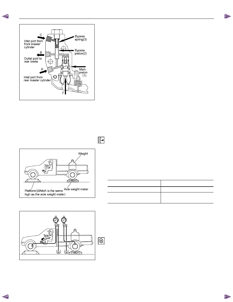
4) Failure on front master cylinder.
In case of failure on front master cylinder the pressure on
the inlet port (C) drop to zero. The pressure from inlet port
(A) acts on the bypass piston (2) and move it by comprising
of bypass spring (3). It makes possible the communication
between the inlet port (A) to outlet port (B) through the
bypass system. The outlet pressure (B) reaches the inlet
pressure (A) and the LSPV is bypassed.
Valve Maintenance
In the case to fluid lead or other a abnormalities, faulty valve
should be replaced.
Note:
The load sensing proportioning valve is not repairable and
must be replaced as a completed assembly.
LOAD SENSING PROPORTIONING
VALVE (LSPV) ADJUSTMENT
RTW35CSH000301
1. Fluid Pressure Measurement
1) Rear axle weight adjustment
With an axle weight meter, adjust the rear axle weight
with a person sitting in the driver’s seat and a weight
loaded in the rear body.
N (kg/lb)
MODEL Adjustment
value
4
× 2
7845 (800/1764)
4
× 2 HIGH RIDE
4
× 4
9316 (950/2095)
RTW35CSH000101
2) Installation of a fluid pressure gauge
Remove the air bleeder of the left hand wheel front and
rear brakes. Bleed air out of the fluid pressure gauge
with the measurement hose of the fluid pressure gauge
installed.
Pressure Tester: Brake oil (Fluid pressure gauge)
5-8840-2190-0
5C-24 BRAKES
RTW35CSH000201
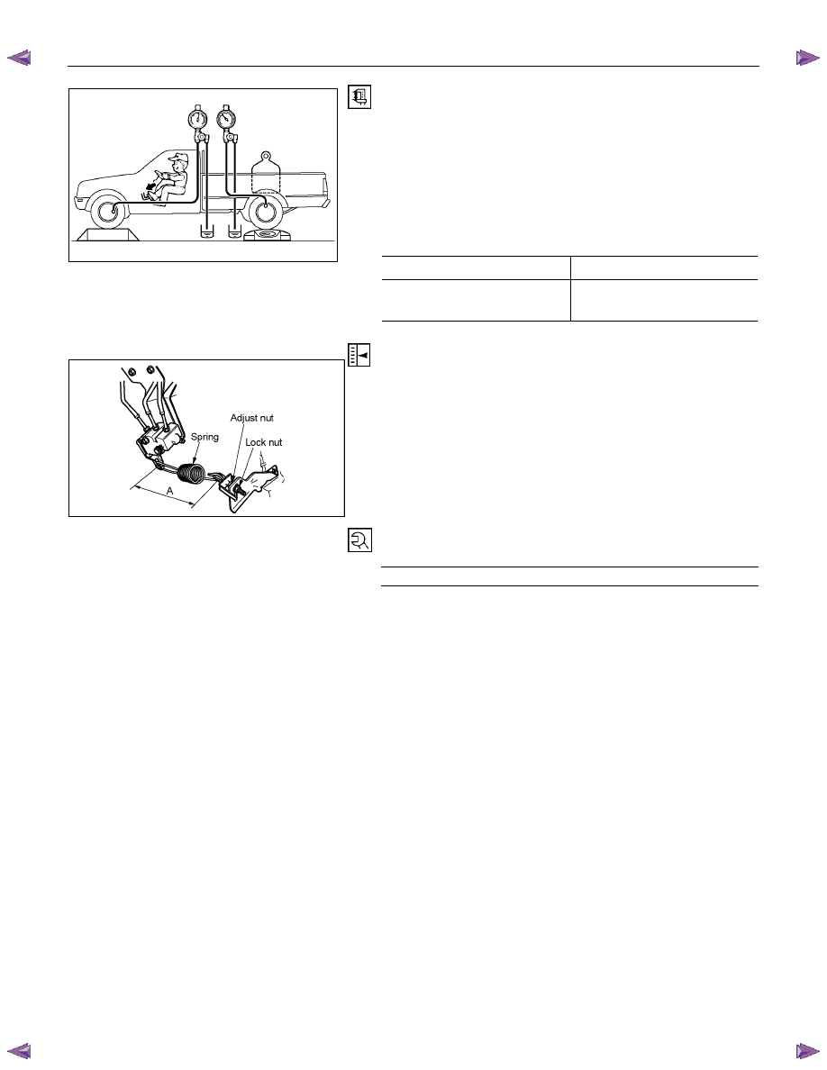
3) Rear wheel cylinder fluid pressure measurement
Step on the brake pedal until the fluid pressure of the
front wheel cylinder gets to 9.8Mpa (100kg/cm
2
), and
check the rear wheel cylinder fluid pressure. (Read the
value of the front wheel cylinder fluid pressure 2
seconds after the measurement. When measuring the
LSPV fluid pressure, keep the brake pedal pressed
down without stepping it down twice or releasing it.)
Rear Wheel Cylinder Fluid Pressure
MPa (kg/cm
2
)
2WD 6.77
±0.83 (69.0±8.5)
2WD (With High Ride
Suspension), 4WD
6.77
±0.83 (69.0±8.5)
RTW35CSH000401
2. Oil Pressure Adjustment
1) LSPV spring length adjustment
Loosen the adjust nut of the LSPV spring joint, and
adjust the length of the LSPV spring.
When the oil pressure is insufficient, turn the adjust nut
clockwise to extend the span “A”. When the oil pressure
is too high, turn the adjust nut counterclockwise to
reduce the span “A”.
2) After adjustment, tighten the lock nut securely.
Lock Nut Torque
N
⋅m (kgf⋅m/lb⋅ft)
11-20 (1.1-2.0/8-14)
Нет комментариевНе стесняйтесь поделиться с нами вашим ценным мнением.
Текст