Isuzu KB P190. Manual — part 1304
8A-278 ELECTRICAL-BODY AND CHASSIS
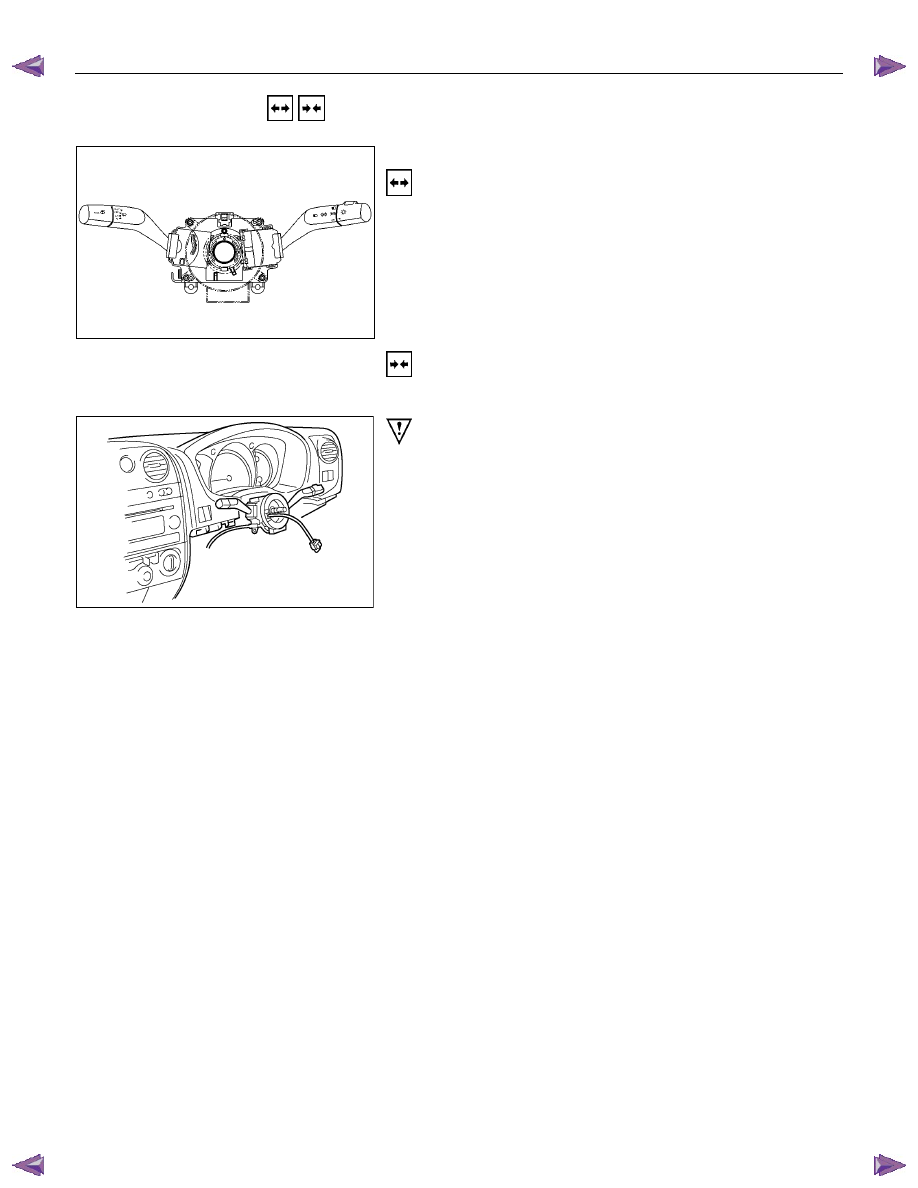
REMOVAL AND INSTALLATION
WIPER AND WASHER SWITCH
Removal
Refer to the removal steps of the LIGHTING SWITCH
(COMBINATION SWITCH) in “ LIGHTING “ of this section.
Installation
Follow the removal procedure in the reverse order to install the
wiper and washer switch.
RTW780SH001601
This illustration is based on RHD model
Pay close attention to the important points mentioned in the
following paragraphs.
Connector
Be absolutely sure that the wiper and washer switch connector
is securely connected.
This will prevent a poor contact and an open circuit.
ELECTRICAL-BODY AND CHASSIS 8A-279
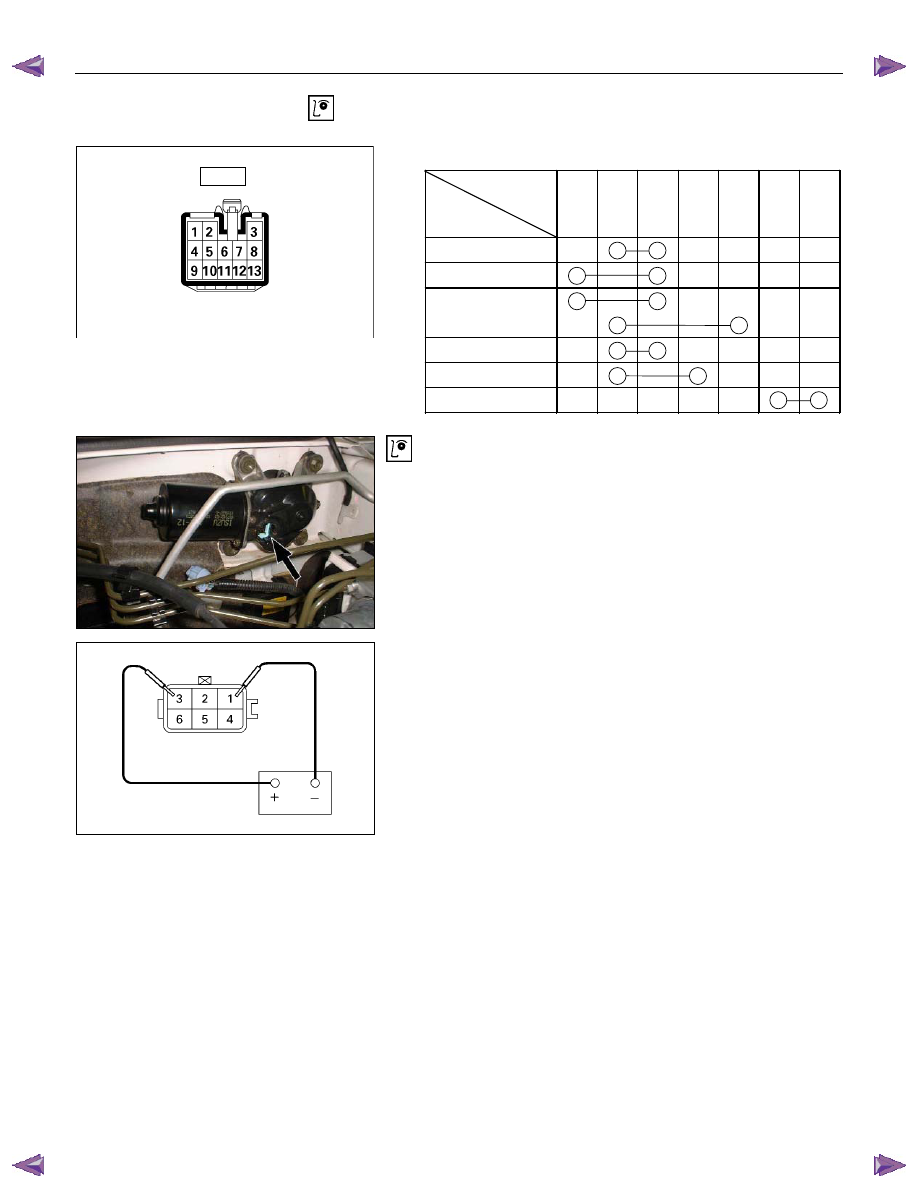
INSPECTION AND REPAIR
Switch side
B59
Control Switch Connections
Terminal
No.
SW position
6 3 5 4 2 7 1
Mist
Off
INT
Lo
Hi
Wash
Wiper Motor Inspection
Connector
Low Speed Inspection
1. Clamp the wiper motor in a vise.
The moving parts must be clear of the vise.
2. Connect the connector terminals to the battery.
Refer to the illustration.
3. Check the wiper motor low speed operation.
8A-280 ELECTRICAL-BODY AND CHASSIS
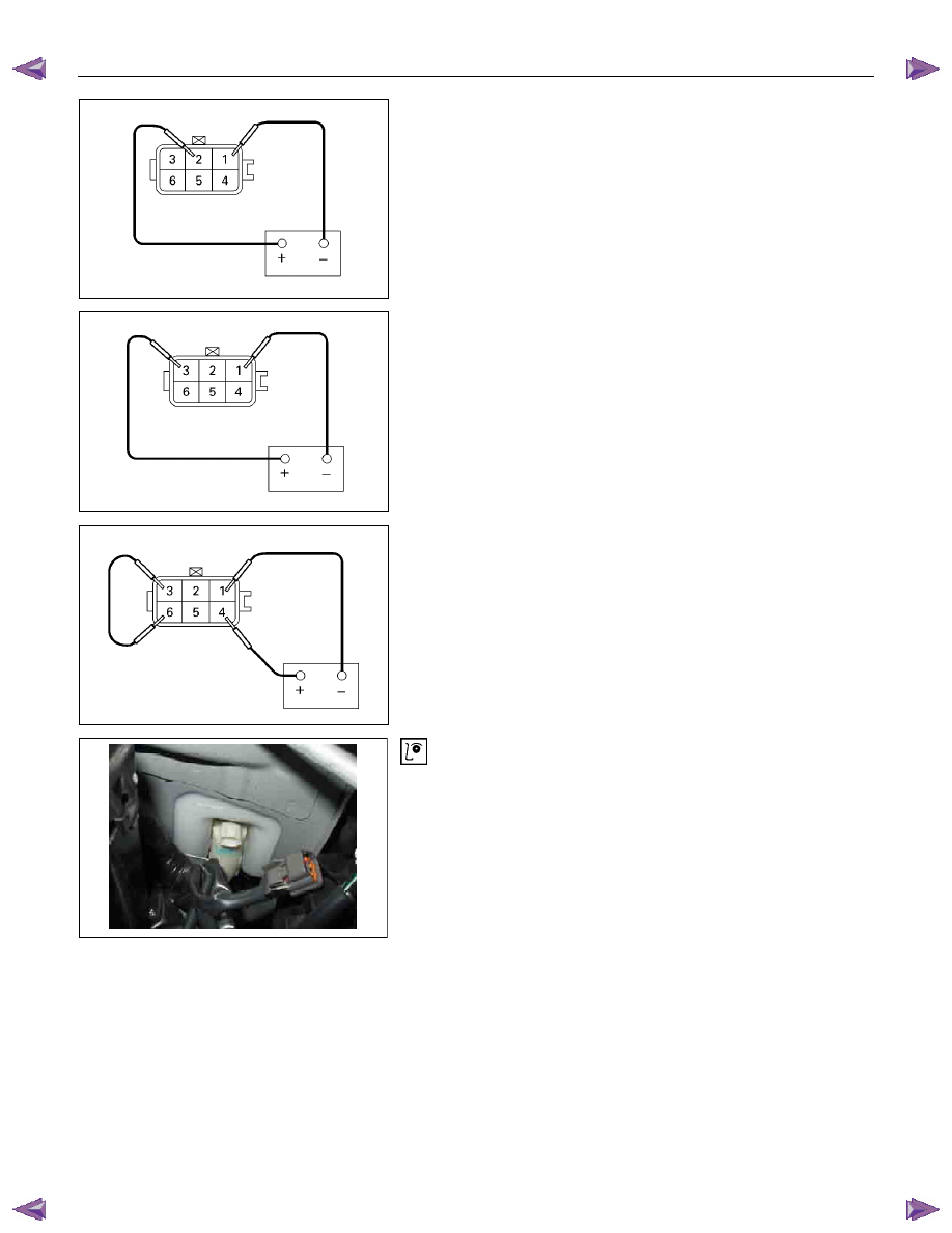
High Speed Inspection
1. Clamp the wiper motor in a vise.
The moving parts must be clear of the vise.
2. Connect the connector terminals to the battery.
Refer to the illustration.
3. Check the wiper motor high speed operation.
Auto-Stop Inspection
1. Clamp the wiper motor in a vise.
The moving parts must be clear of the vise.
2. Connect the connector terminals to the battery.
Refer to the illustration.
3. Check the wiper motor low speed operation.
4. Disconnect the positive battery terminal.
This will stop the motor.
5. Connect the connector terminals No. 3 and No. 6 with a
lead wire.
Refer to the illustration.
6. Reconnect the positive battery terminal to connector
terminal No. 4.
This will restart the motor.
Refer to the illustration.
7. Check the auto-stop operation.
Washer Motor Inspection
1. Fill the washer tank with washing solution.
2. Disconnect the motor connector.
3. Apply battery voltage to the washer motor connector.
4. Check the washer motor operation.
ELECTRICAL-BODY AND CHASSIS 8A-281
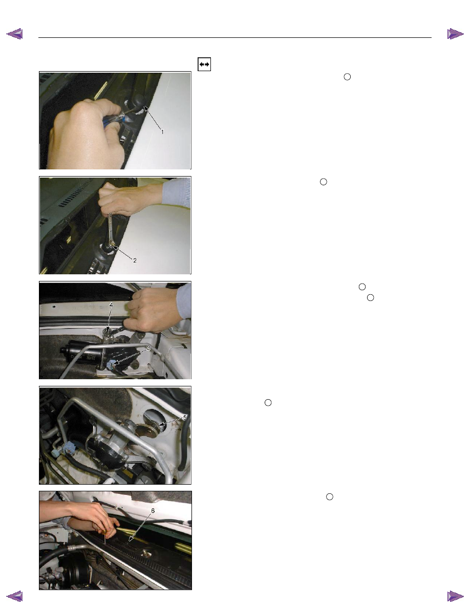
WIPER MOTOR AND LINKAGE
Removal
1. Disconnect the wiper arm nut cap
1
.
2. Remove the wiper arm nut
2
.
3. Remove the wiper arm with blade.
4. Disconnect the wiper motor connector
3
.
5. Remove the wiper motor bracket screws
4
.
6. Disconnect the wiper motor from the wiper linkage at the
crank arm
5
.
7. Remove the vent cowl cover
6
.
• Remove the 6 screw.
Нет комментариевНе стесняйтесь поделиться с нами вашим ценным мнением.
Текст