Isuzu KB P190. Manual — part 1231
7D1-50 TRANSFER CONTROL SYSTEM
6. When shifting from neutral to 2H, 4H or 4L
6-1 When the 4L indicator or 4WD indicator flashes at 2Hz
Indicator flashing at 2Hz indicates that the engagement of the splines has not completed because of deviation
of the spline phases. By eliminating such a deviation, shifting is complete (same as in step 3-1 and 4-1).
6-2 When the 4L indicator or 4WD indicator flashes at 4Hz
As in the case of shifting from 4L to 4H, restriction is imposed to the operation to 4L or 4H (including 2H). If
the transmission lever is at a running range and engine speed is high (3000rpm or more) while the vehicle is
running, operation from neutral of the transfer to the 4L or 4H (including 2H) is impossible (restriction on
operation).
Step 6-2:
Stop the vehicle.
(In case of AT):
Set the transmission select lever to the N (or P) position.
(In case of MT):
Set the transmission lever to the neutral position (at this time, stepping on the clutch
is recommended).
Keep pushing the 4H or 4L or 2H button for 10 seconds.
TRANSFER CONTROL SYSTEM 7D1-51
Trouble diagnosis based on the operation switch, transfer indicator lamp and operating
sound “Check 4WD” indicator ON (operation guard based on the transfer actuator
position detection error)
This condition indicates a faulty circuit related with the detection (limit) switches of the system actuator.
Detection (limit) switches detect the actuator operating angle based on their combinations.
The controller monitors transition of the actuator based on the combination of the detection (limit) switch output.
If the transition based on the combinations indicates some trouble, it is memorized, and shifting operation is
stopped when the trouble is counted 5 times, and the “Check 4WD” indicator lights up. At this time, the system
permits operation to 2H only.
When such a condition occurs, inspection of the transfer shift actuator, checking of the harness related with the
detection (limit) switch, and erasure of the memory of the controller is required.
(Refer to the memory erasure procedure for the erasure of the memory.)
At this time, the position indicator may flash at 4Hz. It means that a detection (limit) switch trouble wad detected
in the operation process shown by that position indicator (example: 4WD indicator when shifting from 2H to 4H).
Caution:
During trouble diagnosis and correction, do not turn ON the ignition with the harness connector of the
transfer actuator disconnected. (Do not disconnect the harness connector of the transfer actuator when
the ignition is ON.)
If the controller is connected during this condition, a limit SW trouble is judged and the above-described
“Check 4WD” condition occurs.
This can be reset by clearing the memory.
When disconnecting the harness connector of the actuator and turning the ignition ON is required, remove
the controller at the same time or remove the IG power fuse of the transfer controller.
7D1-52 TRANSFER CONTROL SYSTEM
Memory erasing procedure
1-1 Memory erasing with operation button
1. Turn on the ignition.
2. Shift to the “N” position with the vehicle stopped.
RTW77DSH000101
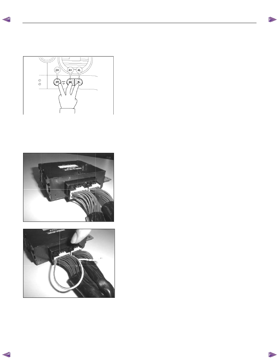
3. Simultaneously push the 3 buttons (2H/4H/4L) for 20
seconds.
4. Confirm the “Check 4WD” indicator on the meter panel is
OFF.
5. Before erasing the memory, check that the circuit of the T/F
actuator position detection harness is normal.
1-2 Memory erasing with short harness (Other procedure)
1. Prepare two pieces of short harness with the end
sharpened like a needle (about 20 cm(7.9 in) long).
2. Turn OFF the ignition.
3. Keeping the connector of the transfer controller connected,
set the short harness from the back of the connector as
illustrated.
4. Turn ON the ignition, wait for 2 seconds, and then turn OFF
the ignition after confirming the relay sound.
5. Disconnect the short harness, turn ON the ignition again,
and confirm the “Check 4WD” lamp on the meter panel is
OFF.
6. Before erasing the memory, check that the circuit of the T/F
actuator position detection harness is normal.
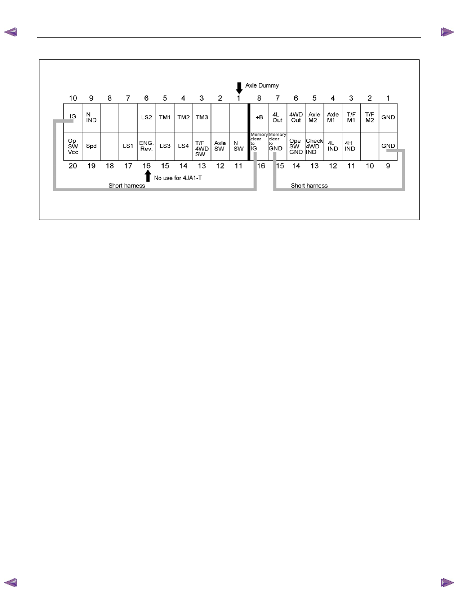
TRANSFER CONTROL SYSTEM 7D1-53
Transfer Controller Pin Assignment
RTW77DSF000101
Нет комментариевНе стесняйтесь поделиться с нами вашим ценным мнением.
Текст