Isuzu KB P190. Manual — part 1185
Manual Transmission (MUX) 7B1-21
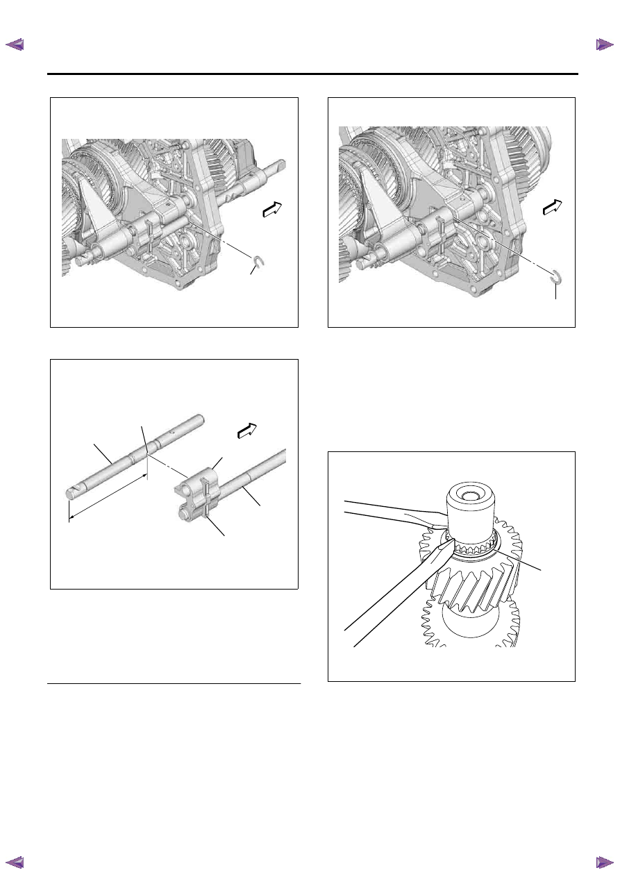
29. Remove the reverse shift rod snap ring (1).
30. The shift block lever is put into the dent of the 3rd-
4th-5th shift rod.
Legend
1. 3rd-4th-5th shift rod
2. Dent of 3rd-4th-5th shift rod
3. 5th-reverse shift block
4. Reverse shift rod
5. Shift block lever
6. 123.5 mm (4.86 in)
31. Remove the reverse shift rod.
32. Remove the reverse shift arm.
33. Use a spring pin remover to remove the 5th shift
arm spring pin.
34. Remove the 3rd-4th-5th shift rod snap ring (1).
35. Remove the 3rd-4th-5th shift rod.
36. Remove the 5th shift arm.
37. Remove the 5th-reverse shift block assembly.
38. Remove the 3rd-4th shift arm assembly.
39. Remove the output shaft assembly.
40. Remove the rubber seal, and discard the used
rubber seal.
41. Remove the counter end snap ring (1).
42. Remove the output counter gear.
43. Remove the pilot bearing.
44. Remove the pilot bearing spacer.
45. Remove the 3rd-4th block ring of the output shaft
side.
46. Remove the plate spring.
RTW77BSH004701
1
RTW77BSH004801
1
6
2
5
4
3
RTW77BSH004901
1
RTW77BSH003701
1
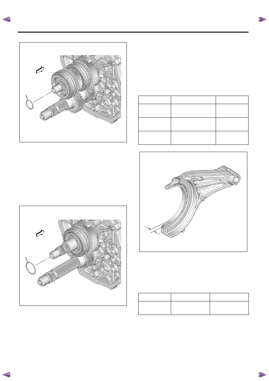
7B1-22 Manual Transmission (MUX)
47. Remove the 3rd-4th hub snap ring (1).
48. Remove the 3rd-4th synchronizer assembly, 3rd-
4th block ring of 3rd input gear side, and 3rd input
gear assembly.
49. Remove the 3rd input gear needle bearing.
50. Remove the 3rd counter gear.
51. Remove the counter shaft assembly and 5th
counter gear from the intermediate plate.
52. Remove the counter middle roller bearing outer
race.
53. Remove the 5th hub snap ring (1).
54. Remove the 5th synchronizer assembly, 5th block
ring and 5th input gear assembly.
55. Remove the 5th input gear needle bearing. (2
piece type)
56. Use a pair of snap ring pliers to hold the input
middle bearing snap ring open .
Push the input shaft assembly toward the front of
the transmission to remove it.
The input middle bearing snap ring will come free.
Inspection and Repair
Make necessary correction or parts replacement if
wear, damage or any other abnormal conditions are
found through inspection.
Shift Arm Thickness
Use a micrometer to measure the shift arm thickness.
If the measured value exceeds the specified limit, the
shift arm must be replaced.
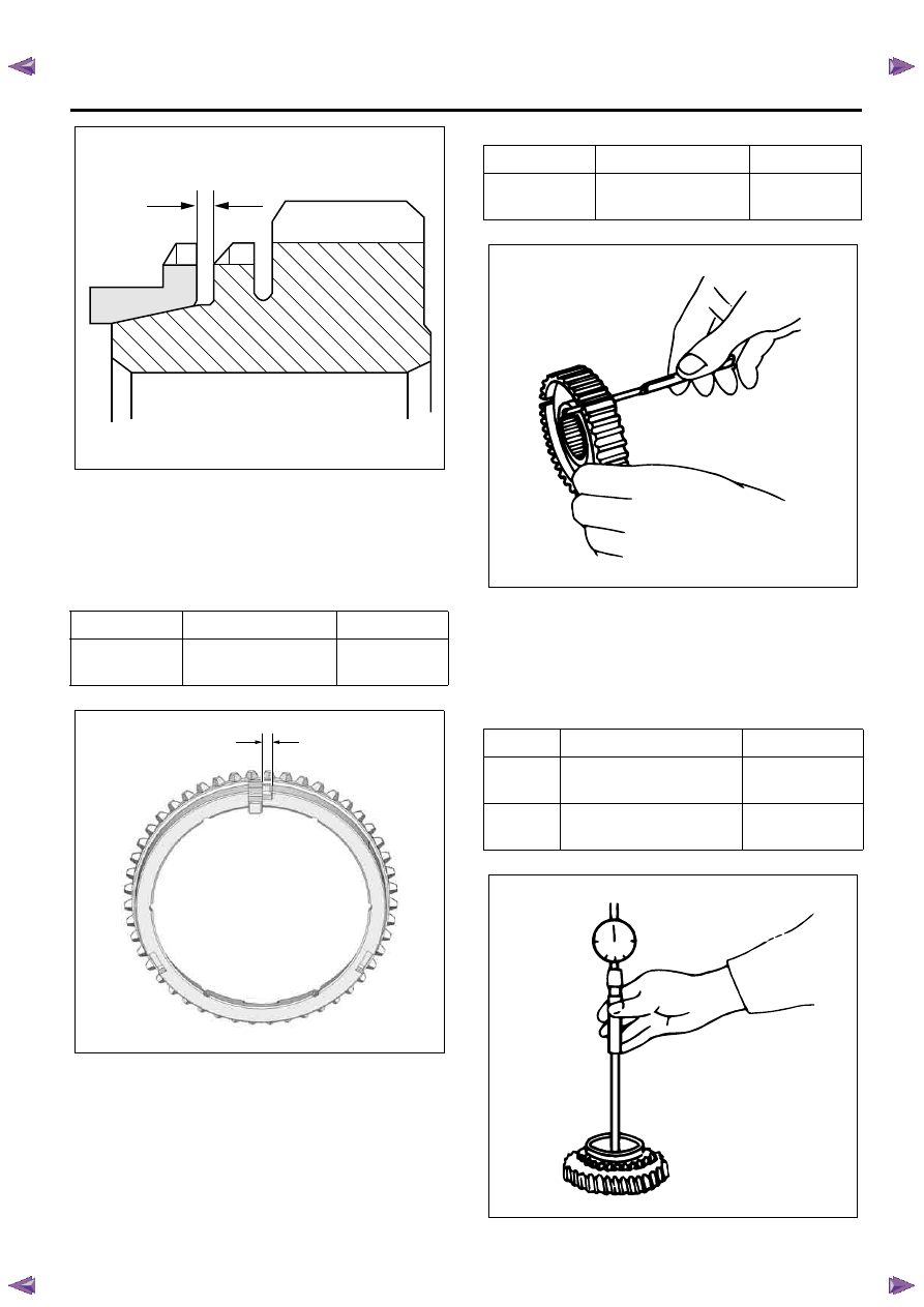
Block Ring and Dog Teeth Clearance
Use a thickness gauge to measure the clearance
between the block ring and the dog teeth.
If the measured value exceeds the specified limit, the
block ring must be replaced.
RTW77BSH005001
1
RTW77BSH005101
1
Standard
Limit
1st - 2nd
3rd - 4th
9.60 - 9.85 mm
(0.378 - 0.388 in)
8.85 mm
(0.348 in)
5th
9.60 - 9.85 mm
(0.378 - 0.388 in)
9.35 mm
(0.368 in)
Reverse
7.85 - 8.10 mm
(0.309 - 0.319 in)
7.60 mm
(0.299 in)
Standard
Limit
3rd - 4th
5th
1.50 mm
(0.059 in)
0.80 mm
(0.031 in)
RTW77BSH006401
Manual Transmission (MUX) 7B1-23
Block Ring and Insert Clearance
Use a vernier caliper or thickness gauge to measure
the clearance between the block ring and insert.
If the measured value exceeds the specified limit, the
block ring and insert must be replaced.
Clutch Hub and Insert Clearance
Use a thickness gauge to measure the clearance
between the clutch hub and insert.
If the measured value exceeds the specified limit, the
clutch hub and insert must be replaced.
Gear Inside Diameter
Use an inside dial indicator to measure the gear inside
diameter.
If the measured value is less than the specified limit,
the gear must be replaced.
Standard
Limit
3rd - 4th
5th
3.59 - 3.91 mm
(0.141 - 0.154 in)
4.10 mm
(0.161 in)
LNW25CSH028401
RTW77BSH006501
Standard
Limit
3rd - 4th
5th
0.09 - 0.31 mm
(0.004 - 0.012 in)
0.40 mm
(0.016 in)
Standard
Limit
3rd
45.000 - 45.016 mm
(1.7717 - 1.7723 in)
45.056 mm
(1.7739 in)
5th
48.000 - 48.016 mm
(1.8898 - 1.8904 in)
48.056 mm
(1.8920 in)
LNW25CSH028701
LNW25CSH028901
7B1-24 Manual Transmission (MUX)
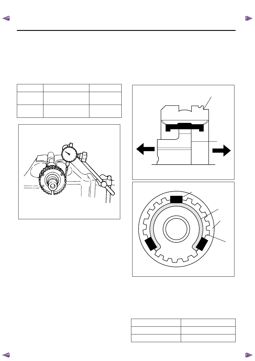
Clutch Hub Spline Play
• Set a dial indicator to the clutch hub to be
measured.
• Move the clutch hub as far as possible to both the
right and the left.
Note the dial indicator reading.
If the measured value exceeds the specified limit, the
clutch hub must be replaced.
Counter Gear Spline Play
Refer to Counter Shaft Assembly in this section.
Installation
1. Use a pair of snap ring pliers to hold the new input
middle bearing snap ring open .
Install the input shaft assembly to the intermediate
plate.
• Never reinstall the used snap ring.
2. Install the input middle bearing snap ring.
3. Install the 5th input gear needle bearing. (2 piece
type)
4. Install the 5th input gear assembly.
• Apply engine oil to the gear internal surface.
5. Assemble the 5th synchronizer assembly by
performing the following steps.
• Turn the clutch hub face (2) toward the sleeve
groove (1) (rear side) on the outer
circumference.
• Check that the inserts (3) fit snugly into the
clutch hub (6) ring insert grooves.
• Check that the inserts springs (4) are fitted to
the inserts as shown in the figure.
• Check that the clutch hub (6) and the sleeve (5)
slide smoothly.
• The insert springs (4) must be set in such a way
that the opening of spring faces different
direction.
6. Install the 5th block ring and 5th synchronizer
assembly.
7. Install the new 5th hub snap ring (1).
• Never reinstall the used snap ring.
• Choose the thickest snap ring among ones
whitch can be assembled.
Snap Ring Availability
Standard
Limit
3rd - 4th
0.010 - 0.102 mm
(0.0004 - 0.0040 in)
0.15 mm
(0.0059 in)
5th
0.009 - 0.104 mm
(0.0004 - 0.0041 in)
0.15 mm
(0.0059 in)
LNW25CSH029101
Thickness
Identification color
1.95 mm(0.077 in)
No color
2.10 mm(0.083 in)
Yellow
1
2
LNW25CSH025601
3
4
5
6
LNW25CSH025701
Нет комментариевНе стесняйтесь поделиться с нами вашим ценным мнением.
Текст