Isuzu KB P190. Manual — part 619
SECTION 6J
INDUCTION
TABLE OF CONTENTS
PAGE
Service Precaution . . . . . . . . . . . . . . . . . . . . . . . . . . . 6J- 2
Air Cleaner Filter. . . . . . . . . . . . . . . . . . . . . . . . . . . . 6J- 2
Removal . . . . . . . . . . . . . . . . . . . . . . . . . . . . . .. 6J- 2
Inspection. . . . . . . . . . . . . . . . . . . . . . . . . . . . ... 6J- 2
Installation. . . . . . . . . . . . . . . . . . . . . . . . . . . . .. 6J- 3
INDUCTION 6J-1
6J-2 INDUCTION
Service Precaution
CAUTION:
Always use the correct fastener in the proper location.
When you replace a fastener, use ONLY the exact part
number for that application. ISUZU will call out those
fasteners that require a replacement after removal. ISUZU
will also call out the fasteners that require thread lockers
or thread sealant. UNLESS OTHERWISE SPECIFIED, do
not use supplemental coatings (Paints, greases, or other
corrosion inhibitors) on threaded fasteners or fastener
joint interfaces. Generally, such coatings adversely affect
the fastener torque and the joint clamping force, and may
damage the fastener. When you install fasteners, use the
correct tightening sequence and specifications. Following
these instructions can help you avoid damage to parts
and systems.
RTW46JSH000101
Air Cleaner Filter
NOTE:
The air cleaner filter is not damaged with the edge of the air
cleaner housing.
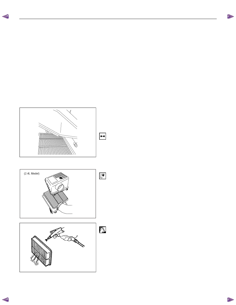
Removal
1. Remove positive ventilation hose connector.
2. Remove intake air temperature sensor.
3. Remove mass air flow sensor.
4. Remove air cleaner duct assembly.
5. Remove air cleaner element.
Inspection
Check the air cleaner filter for damage or dust clogging.
Replace if it is damaged, or clean if it is clogged.
Cleaning Method
Tap the air cleaner filter gently so as not to damage the paper
filter, or clean the element by blowing with compressed air of
about 490 kPa (71 psi) from the clean side if it is extremely
dirty.

INDUCTION 6J-3
Installation
1. Install air cleaner element.
2. Attach the air cleaner duct cover to the body completely,
then clamp it with the clip.
3. Install mass air flow sensor.
4. Install mass air temperature sensor.
5. Install positive crankcase ventilation hose connector.
Section 6A1 Engine Mechanical . . . . . . . . . . . . . . . . . . . . ... 2480
PAGE
Section 6A1 Engine Mechanical Update. . . . . . . . . . . . . . . . . ... 2778
Section 6C1-1 Engine Management General Information . . . . . . . . . . . 3243
Section 6C1-2 Engine Management Diagnostics. . . . . . . . . . . . . . 3279
Section 6C1-3 Engine Management Service Operations . . . . . . . . . . ... 3525
Section 6D1-1 Charging System V6 . . . . . . . . . . . . . . . . . . . 3588
SECTION 6
ENGINE
TABLE OF CONTENTS
Section 6D1-3 Battery V6 . . . . . . . . . . . . . . . . . . . . . . . . 3641
Section 6E1 Powertrain Interface Module V6 . . . . . . . . . . . . . . . .. 3662
HFV6 MODEL
ENGINE
HFV6
Section 6B Engine Cooling . . . . . . . . . . . . . . . . . . . . . . .. 3136
Section 6C Fuel System V6 . . . . . . . . . . . . . . . . . . . . . . .. 3203
Section 6D1-2 Starting System V6 . . . . . . . . . . . . . . . . . . . ... 3609
Section 6F Exhaust System V6 . . . . . . . . . . . . . . . . . . . . . 3749
Нет комментариевНе стесняйтесь поделиться с нами вашим ценным мнением.
Текст