Isuzu KB P190. Manual — part 241
6B – 20 ENGINE COOLING
FAN CLUTCH WITH COOLING FAN
INSPECTION AND REPAIR
Make necessary correction or parts replacement if wear, damage or any other abnormal condition are found through
inspection.
033R300001
Visually inspect for damage, leak (sillicon grease) or other
abnormal conditions.
1. Inspection
(on-vehicle)
1) Turn the fan clutch by hand when in a low temperature
condition before starting the engine, and confirm that it
can be turned readily.
2) Start the engine to warm it up until the temperature at
the fan clutch portion gets to around 80
°C. Then stop
the engine and confirm that the fan clutch can be
turned with considerable effort (clutch torque) when
turned by hand.
If the fan clutch rotates more readily, however, this
indicates that the silicone grease is leaking internally.
Replace the fan clutch with a new one.
033RY00011
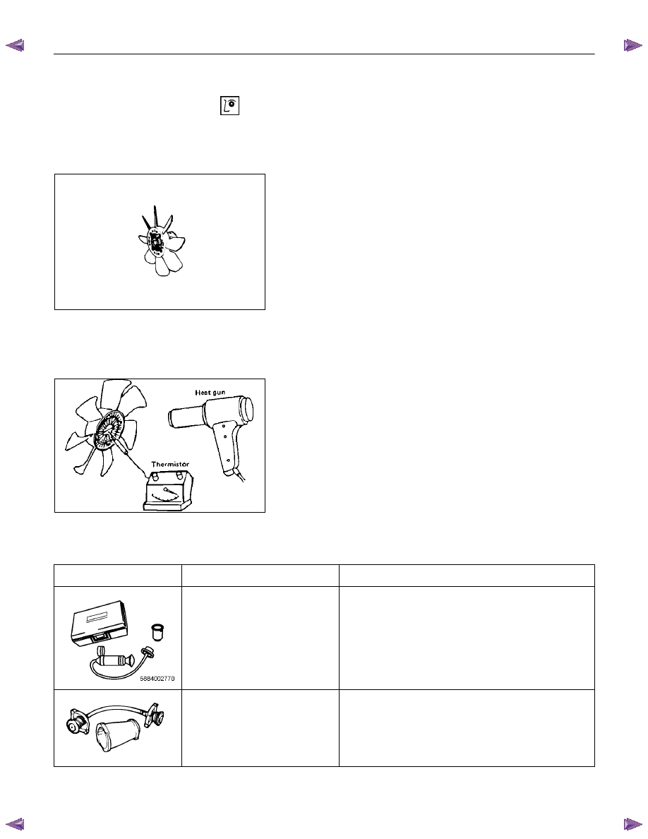
2. Inspection (in unit)
Warm up the bimetal of the fan clutch by using the heat
gun until the temperature gets to about 80
°C when
measured with the thermistor. Then confirm that the fan
clutch can be turned with considerable effort (clutch
torque).
If the fan clutch retates more readily at this time, this
indicates that the silicone grease is leaking internally.
Replace the fan clutch with a new one.
SPECIAL TOOLS
Illustration
Tool Number
Tool Name
5-8840-0277-0 Cap
tester
5-8840-2663-0 Adapter
SECTION 6C
FUEL SYSTEM
TABLE OF CONTENTS
PAGE
Main Data and Specifications. . . . . . . . . . . . . . . . . . . . . ... 6C - 2
General Description . . . . . . . . . . . . . . . . . . . . . . . . . .. 6C - 3
Fuel Flow. . . . . . . . . . . . . . . . . . . . . . . . . . . . . 6C - 3
Fuel Filter and Water Separator . . . . . . . . . . . . . . . . . . . ... 6C - 4
Injection Pump. . . . . . . . . . . . . . . . . . . . . . . . . . ... 6C - 6
Injection Nozzle . . . . . . . . . . . . . . . . . . . . . . . . . . . 6C - 7
Fuel Tank. . . . . . . . . . . . . . . . . . . . . . . . . . . . . . 6C - 8
. . . . . . . . . . . . . . . . . . . . . . . . . . . . .
. . . . . . . . . . . . . . . . . . . . . . . . . . . .
Fuel Gauge Unit . . . . . . . . . . . . . . . . . . . . . . . . . . . . 6C - 11
Removal . . . . . . . . . . . . . . . . . . . . . . . . . . . . . .
Installation . . . . . . . . . . . . . . . . . . . . . . . . . . . . .
Fuel Tube / Quick - Connector Fittings. . . . . . . . . . . . . . . . . . 6C - 14
Filler Neck . . . . . . . . . . . . . . . . . . . . . . . . . . . . . .. 6C - 16
Removal . . . . . . . . . . . . . . . . . . . . . . . . . . . . . .
Installation . . . . . . . . . . . . . . . . . . . . . . . . . . . . .
Fuel Filler Cap. . . . . . . . . . . . . . . . . . . . . . . . . . . . 6C - 17
Injection Pump. . . . . . . . . . . . . . . . . . . . . . . . . . . ... 6C - 18
Removal and Installation . . . . . . . . . . . . . . . . . . . . . . .. 6C - 18
Removal . . . . . . . . . . . . . . . . . . . . . . . . . . . . . . 6C - 18
Installation . . . . . . . . . . . . . . . . . . . . . . . . . . . . . 6C - 21
Injection Nozzle (4JA1L) . . . . . . . . . . . . . . . . . . . . . . . ... 6C - 25
Disassembly . . . . . . . . . . . . . . . . . . . . . . . . . . . .. 6C - 25
Reassembly . . . . . . . . . . . . . . . . . . . . . . . . . . . ... 6C - 26
Special tools . . . . . . . . . . . . . . . . . . . . . . . . . . . . .. 6C - 37
FUEL SYSTEM 6C – 1
6C – 2 FUEL SYSTEM
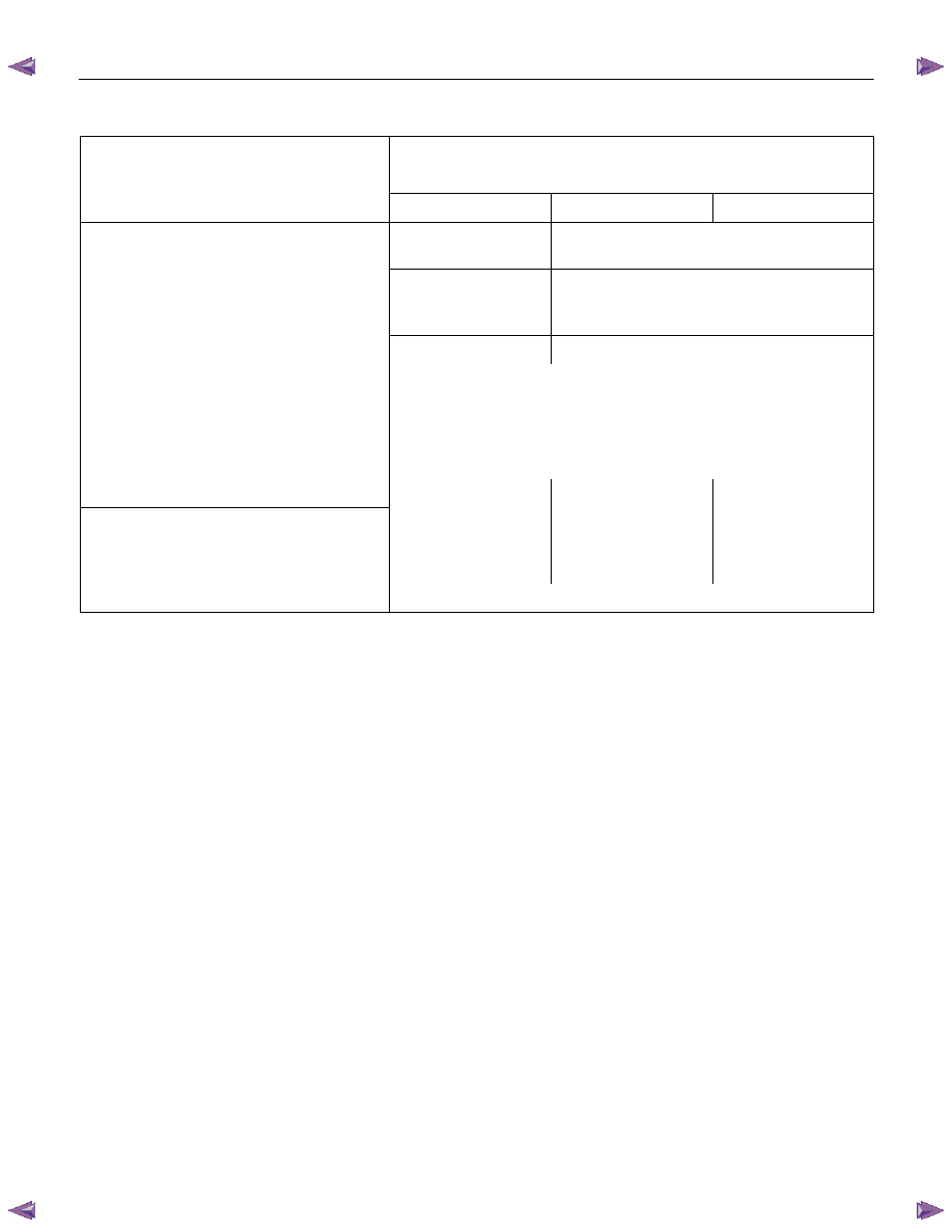
MAIN DATA AND SPECIFICATIONS
Description
Item
4JA1T (L)
4JA1TC
4JH1TC
Injection pump type
Bosch distributor
VE type
Bosch distributor VP44 type
Governor type
Mechanical variable
(Half speed oil
pressure)
Electrical controled
Timer type
Oil pressure
Electrical controled
Fuel feed pump type
Vane with input shaft
Injection nozzle type
Hole type
Number of injection nozzle orifices
5
Injection nozzle orifices
Inside diameter
mm (in)
0.19 (0.0075)
0.17 (0.0067)
0.21 (0.0083)
19.1 (195)
19.0 (194)
19.5 (199)
Injection nozzle designed operating
pressure MPa (kg/cm
2
) 1st
2nd
25.0 (255)
33.5 (328)
33.8 (331)
Main fuel filter type
Disposable cartridge paper element
Precautions
When working on the fuel system, there are several things
to keep in mind:
• Any time the fuel system is being worked on,
disconnect the negative battery cable except for
those tests where battery voltage is required.
• Always keep a dry chemical (Class B) fire
extinguisher near the work area.
• Replace all pipes with the same pipe and fittings that
were removed.
• Clean and inspect “O” rings. Replace if required.
• Always relieve the line pressure before servicing any
fuel system components.
• Do not attempt repairs on the fuel system until you
have read the instructions and checked the pictures
relating to that repair.
• Adhere to all Notices and Cautions.
NOTE:
Injection nozzle adjustment is possible only on the 4JA1L
engine.
FUEL SYSTEM 6C – 3
GENERAL DESCRIPTION
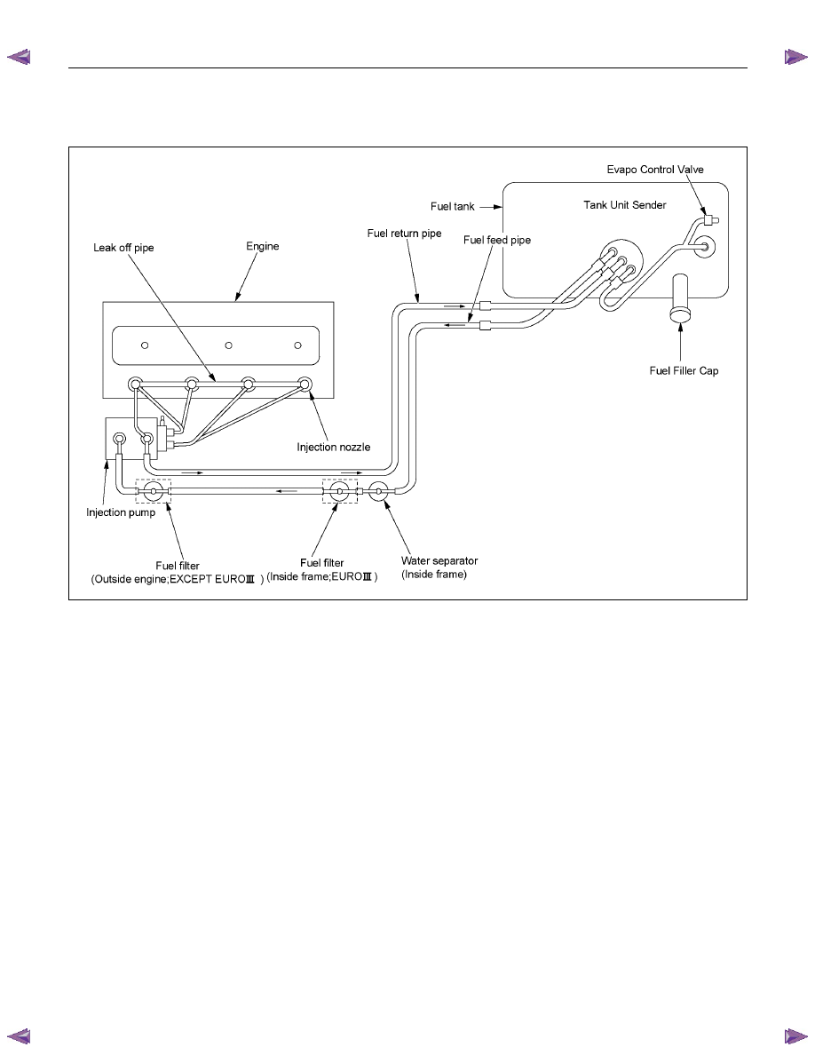
FUEL FLOW
RTW66CMF000101
The fuel system consists of the fuel tank, the fuel filter, the water separator, the injection pump, and the injection
nozzle.
The fuel from the fuel tank passes through the water separator and the fuel filter where water particles and other
foreign material are removed from the fuel.
Fuel, fed by the injection pump plunger, is delivered to the injection nozzle in the measured volume at the optimum
timing for efficient engine operation.
NOTE:
1 If it find abnormal condition on the fuel injector, refer to section 6E ENGINE DRIVEABILITY AND
EMISSIONS.
2
Do not contain "Additive for water drain" with fuel.
Нет комментариевНе стесняйтесь поделиться с нами вашим ценным мнением.
Текст