Isuzu KB P190. Manual — part 406
ENGINE CONTROL SYSTEM (4JK1/4JJ1) 6E-7
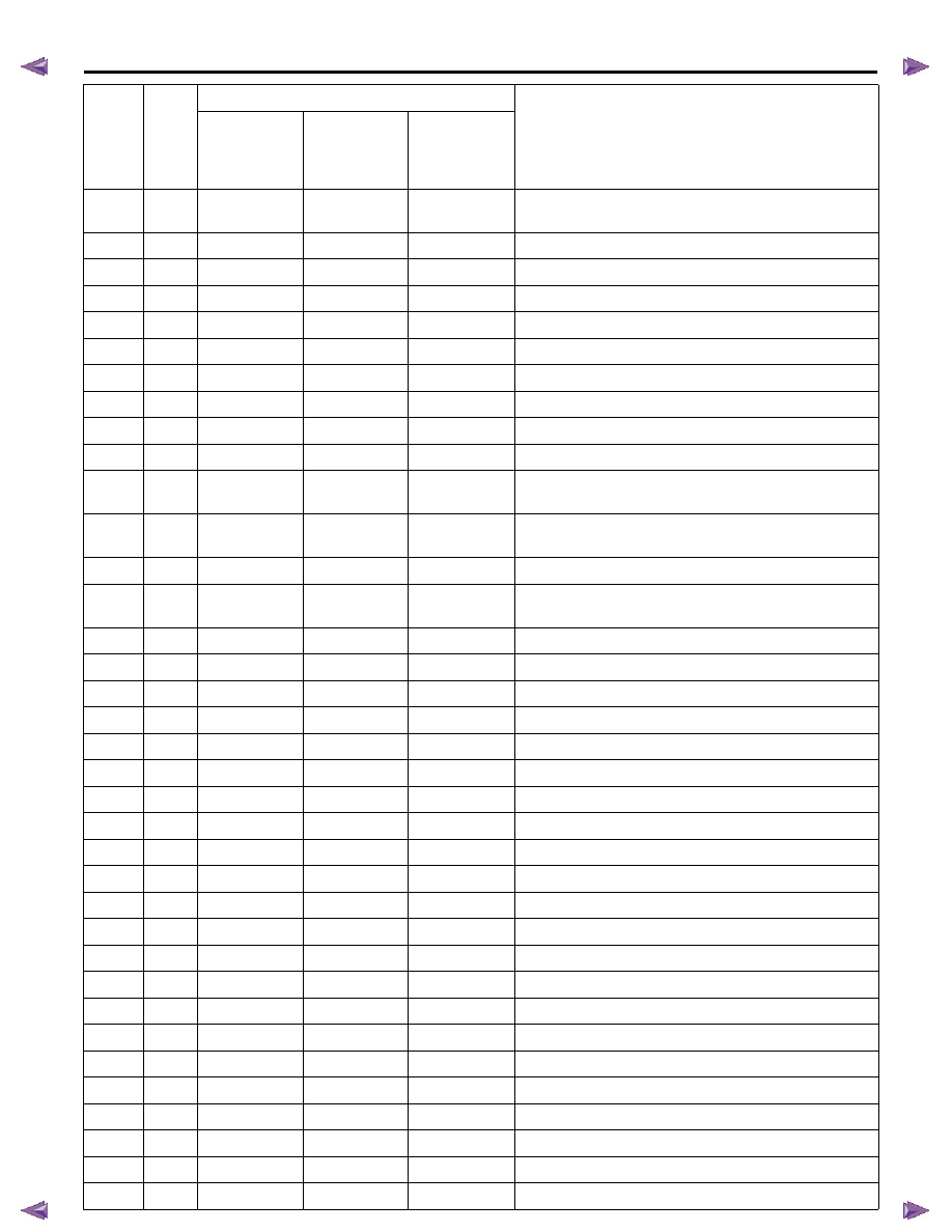
P1261
34
C
A
A
Injector Positive Voltage Control Circuit (Supply Voltage
High)
P1262
34
A
A
A
Injector Positive Voltage Control Circuit Group 2
P1404
45
A
A
A
EGR Position Fault (Closed Position Error)
P1404
45
A
-
-
EGR Position Fault (Learned Position Error)
P1411
445
A
A
A
EGR Solenoid Control Driver
P1412
445
A
A
A
EGR Solenoid Control Driver
P1413
445
A
A
A
EGR Solenoid Control Driver
P156A
135
C
A
A
Battery Voltage Low
P156B
135
C
A
A
Battery Voltage High
P161B
179
C
A
A
Immobilizer Wrong Response
P1621
54
C
A
A
Control Module Long Term Memory Performance
(Learned Data)
P1621
254
C
A
A
Control Module Long Term Memory Performance (VIN or
Immobilizer Data)
P1664
76
D
-
-
Service Vehicle Soon Lamp Control Circuit (Low Voltage)
P1664
76
C
-
-
Service Vehicle Soon Lamp Control Circuit (High
Voltage)
P2100
446
B
A
A
Intake Throttle Solenoid Circuit Open
P2101
446
B
A
A
Intake Throttle Solenoid Circuit Low
P2103
446
B
A
A
Intake Throttle Solenoid Circuit High
P2122
121
C
A
A
Pedal Position Sensor 1 Circuit Low Input
P2123
121
C
A
A
Pedal Position Sensor 1 Circuit High Input
P2127
122
C
A
A
Pedal Position Sensor 2 Circuit Low Input
P2128
122
C
A
A
Pedal Position Sensor 2 Circuit High Input
P2132
123
C
A
A
Pedal Position Sensor 3 Circuit Low Input
P2133
123
A
A
A
Pedal Position Sensor 3 Circuit High Input
P2138
124
C
A
A
Pedal Position Sensor 1 - 2 Voltage Correlation
P2139
125
C
A
A
Pedal Position Sensor 1 - 3 Voltage Correlation
P2140
126
C
A
A
Pedal Position Sensor 2 - 3 Voltage Correlation
P2146
158
A
A
A
Fuel Injector Group 1 Supply Voltage Circuit Short
P2147
158
A
A
A
Fuel Injector Group 1 Supply Voltage Circuit Low
P2148
158
A
A
A
Fuel Injector Group 1 Supply Voltage Circuit High
P2149
159
A
A
A
Fuel Injector Group 2 Supply Voltage Circuit Short
P2150
159
A
A
A
Fuel Injector Group 2 Supply Voltage Circuit Low
P2151
159
A
A
A
Fuel Injector Group 2 Supply Voltage Circuit High
P2227
71
A
A
-
Barometric Pressure Sensor Circuit Range/ Performance
P2228
71
A
A
A
Barometric Pressure Sensor Circuit Low
P2229
71
A
A
A
Barometric Pressure sensor Circuit High
P2621
94
-
-
A
Throttle Position Output Circuit Low
DTC
Flash
Code
DTC Type
DTC Descriptor
Euro 4
Specification
Except Euro 4
Specification
(High Output)
Except Euro 4
Specification
(Standard
Output)
6E-8 ENGINE CONTROL SYSTEM (4JK1/4JJ1)
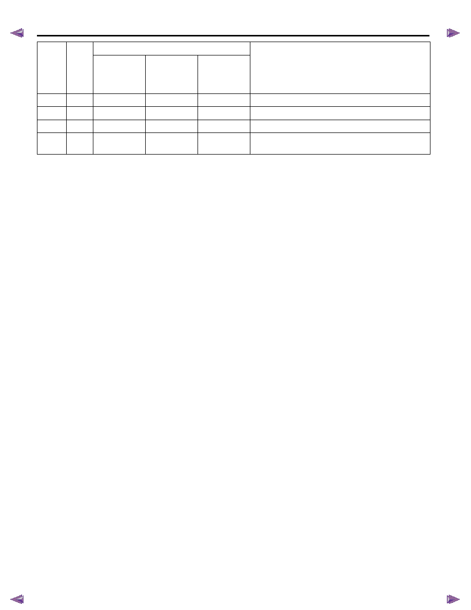
P2622
94
-
-
A
Throttle Position Output Circuit High
U0001
84
A
A
A
High Speed CAN Communication Bus
U0101
85
A
A
-
Lost Communication with TCM
U0167
177
C
A
A
Lost Communication With Vehicle Immobilizer Control
Module
DTC
Flash
Code
DTC Type
DTC Descriptor
Euro 4
Specification
Except Euro 4
Specification
(High Output)
Except Euro 4
Specification
(Standard
Output)
ENGINE CONTROL SYSTEM (4JK1/4JJ1) 6E-9
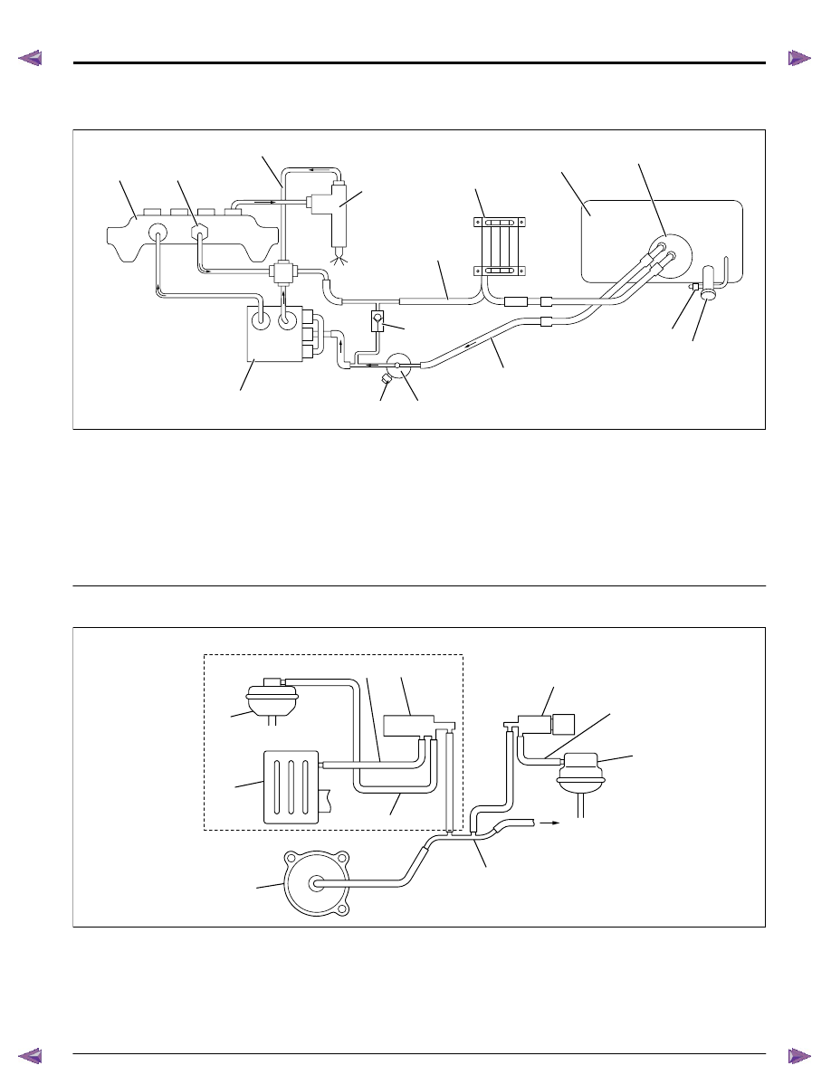
Schematic and Rounting Diagrams
Fuel System Routing Diagram
Legend
1. Fuel rail
2. Fuel pressure limiter
3. Leak off pipe
4. Fuel injector
5. Fuel return pipe
6. Fuel cooler
7. Fuel tank
8. Fuel pump and sender assembly
9. Fuel filler cap
10. Vent valve
11. Fuel feed pipe
12. One-way valve
13. Fuel filter with sedimenter
14. Fuel pressure switch
15. Fuel supply pump
Vacuum Hose Routing Diagram
Legend
1. Swirl control solenoid valve
2. Actuator control vacuum hose
3. Swirl control actuator
4. Brake booster
5. Vacuum pipe
6. Vacuum pump
7. Actuator control vacuum hose
8. Air cleaner
9. Turbocharger nozzle control actuator
10. Solenoid valve ventilation hose
11. Turbocharger nozzle control solenoid valve
RTW76ESF000101
1
2
3
4
5
11
7
8
9
10
14
13
12
15
6
RTW76ESF000201
1
2
4
5
6
9
8
3
7
11
High output
10
6E-10 ENGINE CONTROL SYSTEM (4JK1/4JJ1)
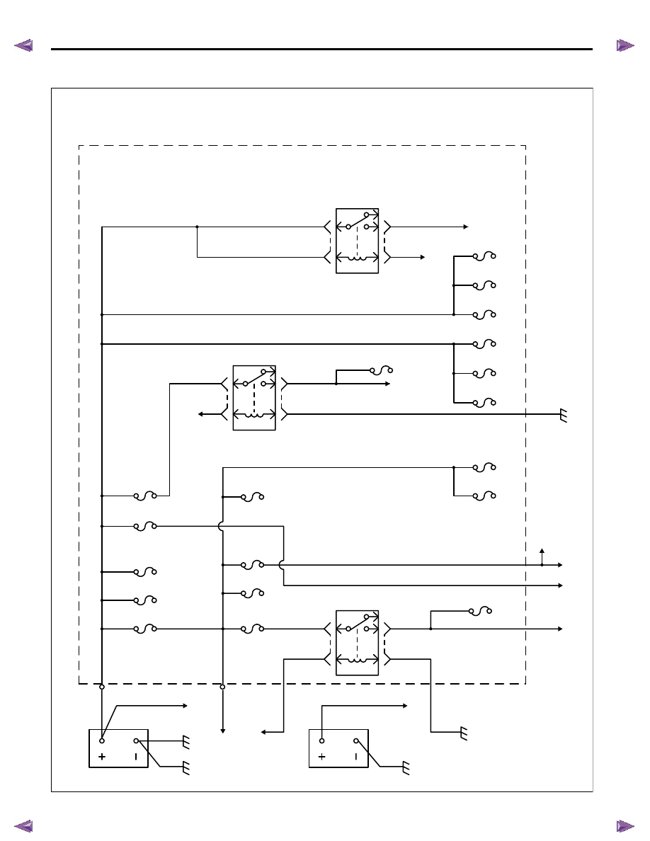
Engine Controls Schematics
Power Distribution (1)
RTW76EXF003601
X-11
X-11
Heater relay
1
2
Blower motor
Ignition switch
Ignition switch
Starter relay
SBF1 Main 120A
SBF2 ABS-1 40A
SBF3 ABS-2 20A
SBF5 IG1 40A
SBF4 ECM 40A
SBF6 Blower 30A
EB-13 A/C 10A
2 BLU/ RED
3 BLU/ RED
3 BLU/ RED
SBF8 Glow 60A
SBF7 Front Fog 20A
SBF9 IG2 60A
EB-9 Fog 15A or Trailer 20A
EB-10 Tail/Illumi 10A or Condenser fan 20A
EB-4 Engine 10A
EB-14 4WD 10A
EB-15 Horn 10A
EB-16 Hazard 10A
EB-1 ACG (S) 10A
EB-2 ECM (B) 10A
EB-3 F/Pump 10A
EB-5
H/L
HI(RH)10A
Fuse
EB-6
H/L
HI(LH)10A
Fuse
EB-7
H/L
LO(RH)10A
Fuse
EB-8
H/L
LO(LH)10A
Fuse
P-6 Body
Generator
P-5
8
BLK/
P-1
P-2
Battery
8 BLK
5WHT
Srarter
Srarter
C-3 ELEC
IG
10A Fuse
E-92
0.5
WHT
0.3 BLK
3 WHT/ RED
5 WHT
0.3 BLK
5 RED/ BLU
5 RED
3 WHT/ BLK
30 BLK/ RED
30 BLK/ YEL
P-10 Engine
5
4
X-12
X-12
ECM Fuel
pump
relay
ECM
ECM main relay
1
2
5
4
X-6
X-6
2 RED/ WHT
0.3 RED/ BLU
Fuse/
relay
box(Engine
room)
2 RED
2 RED
0.5 RED
2 WHT
2 RED/ BLU
2 WHT
2
3
1
5
Lighting switch
Head lamp relay
C-36
C-36
RED
P-16
P-15
2nd Battery
30 BLK/ YEL
30 BLK/ RED
P-10
Нет комментариевНе стесняйтесь поделиться с нами вашим ценным мнением.
Текст