Isuzu KB P190. Manual — part 696

Engine Mechanical – V6
Page 6A1–7
Page 6A1–7
Left-hand Cylinder Head Intake Face . . . . . . . . . . . . . . . . . . . . . . . . . . . ... 324
Left-hand Cylinder Head Exhaust Face . . . . . . . . . . . . . . . . . . . . . . .... . . . 325
Left-hand Cylinder Head Rear Face . . . . . . . . . . . . . . . . . . . . . . . ... . . . ... 326
Right-hand Cylinder Head Camshaft Cover Face . . . . . . . . . . . . . . . . . . . . .... . 327
Right-hand Cylinder Head Front Face. . . . . . . . . . . . . . . . . . . . . . . . . . . .. 328
Right-hand Cylinder Head Intake Face . . . . . . . . . . . . . . . . . . . . . . .... . . . . 329
Right-hand Cylinder Head Exhaust Face . . . . . . . . . . . . . . . . . . . . . . ... . . ... 330
Right-hand Cylinder Head Rear Face . . . . . . . . . . . . . . . . . . . . . . . .. . . . .. 331
Engine Block Front . . . . . . . . . . . . . . . . . . . . . . . . . . . .. . . . . . . ... 332
Engine Block Left-hand Side . . . . . . . . . . . . . . . . . . . . . . . . . . . . . . . 333
Engine Block Right-hand Side. . . . . . . . . . . . . . . . . . . . . . . . .... . . . . ... 334
Engine Block Rear . . . . . . . . . . . . . . . . . . . . . . . . . . . ... . . . . . . ... 335
Engine Block Bottom. . . . . . . . . . . . . . . . . . . . . . . . . . . . . . . . . . . 336
Engine Block Left-hand Deck Face . . . . . . . . . . . . . . . . . . . . . . . .... . . . ... 337
Engine Block Right-hand Deck Face. . . . . . . . . . . . . . . . . . . . . . . ... . . . .. 338
Engine Front Cover. . . . . . . . . . . . . . . . . . . . . . . . . . . .. . . . . . . ... 339
Upper Intake Manifold Top . . . . . . . . . . . . . . . . . . . . . . . . . ... . . . . . .. 340
Upper Intake Manifold Front . . . . . . . . . . . . . . . . . . . . . . . . . . . . . . . . 341
Upper Intake Manifold Rear. . . . . . . . . . . . . . . . . . . . . . . . . .. . . . . . .. 342
Lower Intake Manifold Top. . . . . . . . . . . . . . . . . . . . . . . . . ... . . . . . .. 343
Oil Pan Front . . . . . . . . . . . . . . . . . . . . . . . . . . . . ... . . . . . . . . 344
Oil Pan Rear. . . . . . . . . . . . . . . . . . . . . . . . . . . . .... . . . . . . . . . 345
Oil Pan Bottom . . . . . . . . . . . . . . . . . . . . . . . . . . . . .. . . . . . . . .. 346
Specifications . . . . . . . . . . . . . . . . . . . . . . . . . . . . .. . . . . 347
Torque Wrench Specifications. . . . . . . . . . . . . . . . . . . . . . . . .... ...351
Special Tools . . . . . . . . . . . . . . . . . . . . . . . . . . . . ... . . . . 353
Engine Mechanical – V6
Page 6A1–8
Page 6A1–8
1 General
Information
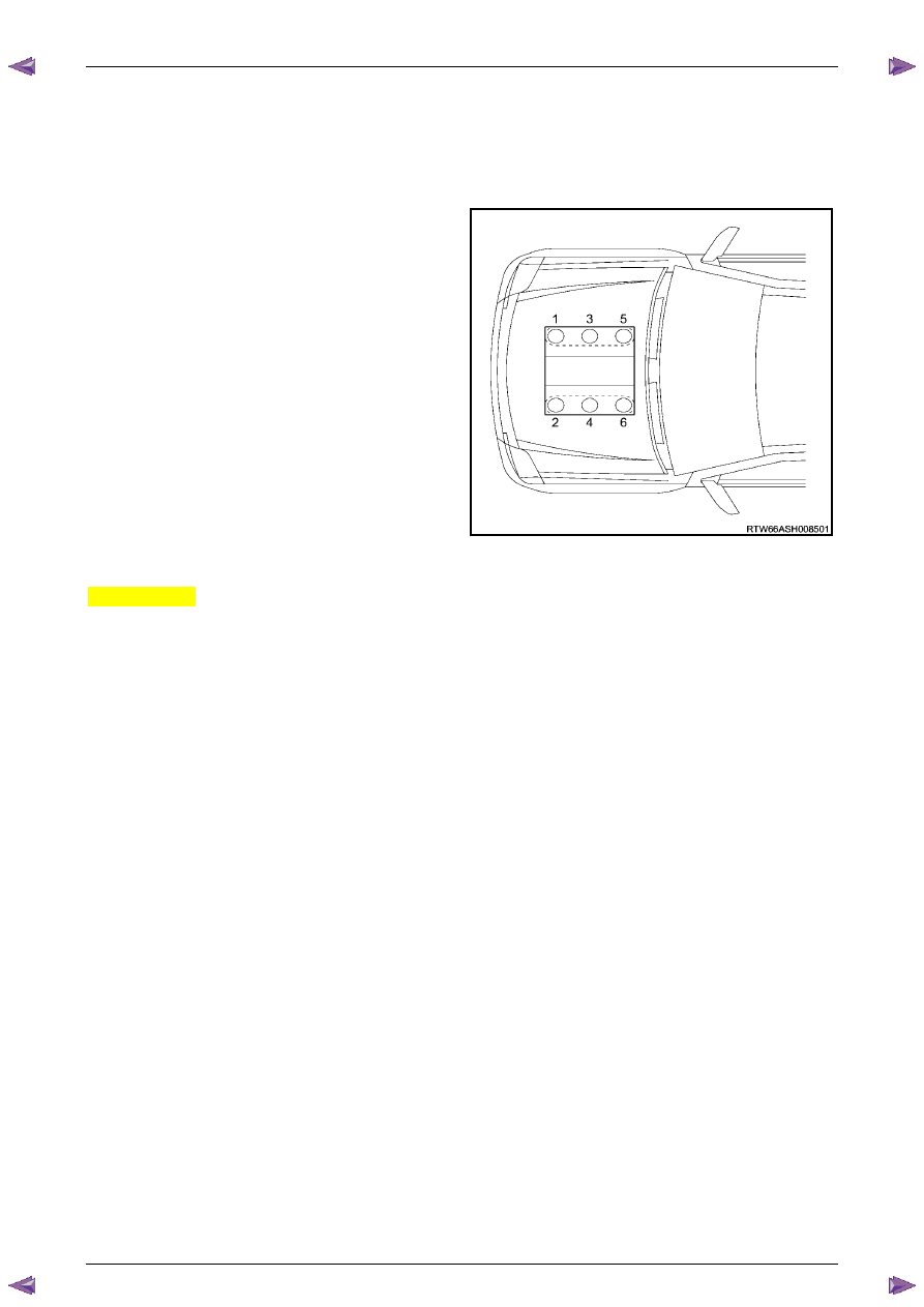
The HFV6 engine features a closed vee, deep skirt die cast aluminium cylinder block with cast iron cylinder liners,
internally balanced crankcase, full length water jackets and six bolt main bearing caps.
The cylinders are arranged in two banks of three with a 60 degree included angle between the two banks.
The right-hand bank of cylinders consists of number 1-3-5
cylinders and the left-hand bank of cylinders consists of
number 2-4-6.
The engine firing order is 1-2-3-4-5-6.
Each aluminium cylinder head is fitted with hardened valve
seats and four valves per cylinder: two intake and two
exhaust.
The valves are operated by two camshafts (DOHC) per
cylinder bank, one each for intake and exhaust valves.
The crankshaft is manufactured from forged steel. A reluctor
wheel is pressed in place onto the rear of the crankshaft for
the crankshaft position sensor.
The connecting rods are manufactured from powdered
metal and the rod cap is separated during the manufacturing
process using the fractured method. This creates a stronger,
visually seamless rod to cap union.
Figure 6A1 – 1
MY06 Update
Throughout this Section, reference is made to 'MY06 Update' or 'Excluding MY06 Update'.
Vehicles manufactured post 14th March 2007 are fitted with an updated version of the HFV6 engine. This engine
features a different timing chain, and as a result different sprocket teeth. This change also introduces the use of a new
special tool to assist in the serviceability of replacing the engine timing components.
All service procedures and descriptions specific to this update variation are qualified as 'MY06 Update'.
1.1
WARNING, CAUTION and NOTES
This Section contains various WARNINGS, CAUTIONS and NOTE statements that you must observe carefully to reduce
the risk of death or injury during service, repair procedures or vehicle operation. Incorrect service or repair procedures
may damage the vehicle or cause operational faults. WARNINGS, CAUTION and NOTE statements are not exhaustive.
HOLDEN LTD can not possibly warn of all the potentially hazardous consequences of failure to follow these instructions.
Definition of WARNING, CAUTION and NOTE Statements
Diagnosis and repair procedures in this Section contain both general and specific WARNING, CAUTION and NOTE
statements. HOLDEN LTD is dedicated to the presentation of service information that helps the technician to diagnose
and repair the systems necessary for proper operation of the vehicle. Certain procedures may present a hazard to the
technician if they are not followed in the recommended manner. WARNING, CAUTION and NOTE statements are
designed to help prevent these hazards from occurring, but not all hazards can be foreseen.
WARNING defined
A WARNING statement immediately precedes an operating procedure or maintenance practice which, if not correctly
followed, could result in death or injury. A WARNING statement alerts you to take necessary action or not to take a
prohibited action. If a WARNING statement is ignored, the following consequences may occur:
•
Death or injury to the technician or other personnel working on the vehicle,
•
Death or injury to other people in or near the workplace area, and / or
•
Death or injury to the driver / or passenger(s) of the vehicle or other people, if the vehicle has been improperly
repaired.
CAUTION defined
A CAUTION statement immediately precedes an operating procedure or maintenance practice which, if not correctly
followed, could result in damage to or destruction of equipment, or corruption of data. If a CAUTION statement is
ignored, the following consequences may occur:
•
Damage to the vehicle,
•
Unnecessary vehicle repairs or component replacement,

Engine Mechanical – V6
Page 6A1–9
Page 6A1–9
•
Faulty operation or performance of any system or component being repaired,
•
Damage to any system or components which depend on the proper operation of the system or component being
repaired,
•
Faulty operation or performance of any systems or components which depend on the proper operation or
performance of the system or component under repair,
•
Damage to fasteners, basic tools or special tools and / or
•
Leakage of coolant, lubricant or other vital fluids.
NOTE defined
A NOTE statement immediately precedes or follows an operating procedure, maintenance practice or condition that
requires highlighting. A NOTE statement also emphasises necessary characteristics of a diagnostic or repair procedure.
A NOTE statement is designed to:
•
Clarify a procedure,
•
Present additional information for accomplishing a procedure,
•
Give insight into the reasons for performing a procedure in the recommended manner, and / or
Present information that gives the technician the benefit of past experience in accomplishing a procedure with greater
ease.
Engine Mechanical – V6
Page 6A1–10
Page 6A1–10
1.2 Engine
Components
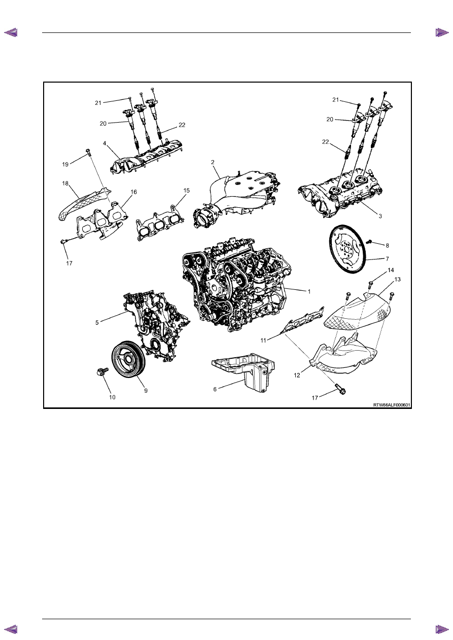
Major Component Assemblies
Figure 6A1 – 2
Legend
1 Engine
Assembly
2
Intake Manifold Assembly
3
Camshaft Cover Assembly, Left-hand
4
Camshaft Cover Assembly, Right-hand
5
Engine Front Cover Assembly
6
Oil Pan Assembly
7 Engine
Flywheel
8
Engine Flywheel Bolt
9 Crankshaft
Balancer
10
Crankshaft Balancer Bolt
11
Exhaust Manifold Gasket, Left-hand
12
Exhaust Manifold, Left-hand
13
Exhaust Manifold Heat Shield, Left-hand
14
Exhaust Manifold Heat Shield Bolt, Left-hand
15
Exhaust Manifold Gasket, Right-hand
16
Exhaust Manifold, Right-hand
17
Cylinder Head Exhaust Manifold Bolt
18
Exhaust Manifold Heat Shield, Right-hand
19
Exhaust Manifold Heat Shield Bolt, Right-hand
20
Ignition Coil Assembly
21
Ignition Coil Assembly Bolt
22 Spark
Plug
Нет комментариевНе стесняйтесь поделиться с нами вашим ценным мнением.
Текст