Isuzu KB P190. Manual — part 1410
SUPPLEMENTAL RESTRAINT SYSTEM 9A-5
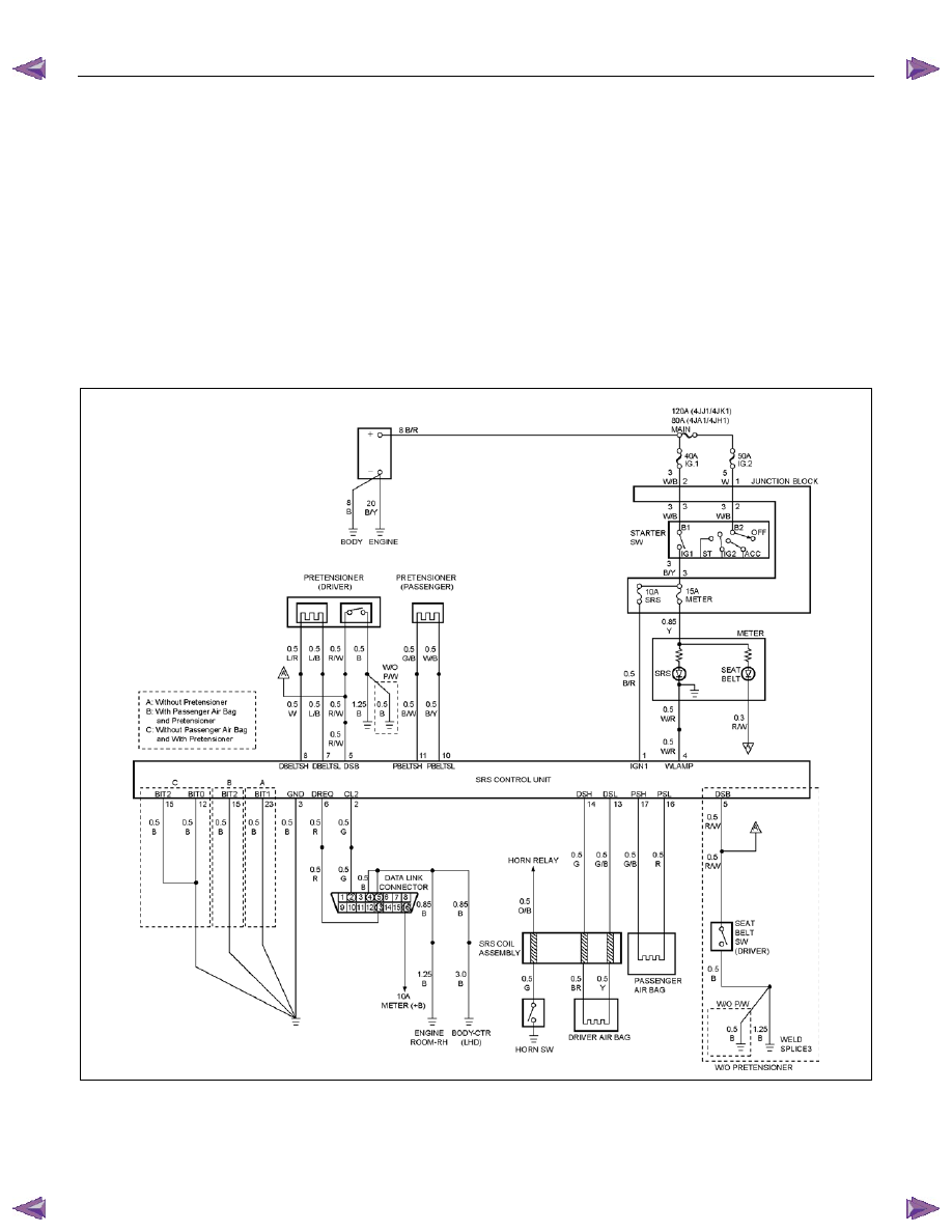
System Description
The SRS consists of the SRS control unit, the driver
air bag assembly, the SRS coil assembly, the
passenger air bag assembly and the “SRS” warning
lamp in the instrument cluster. The SRS control unit,
SRS coil assembly (driver side only), driver air bag
assembly, passenger air bag assembly and connector
wire make up the deployment loops. The function of
the deployment loops is to supply current through the
air bag assembly, which will cause deployment of the
air bags in the event of a frontal crash of sufficient
force, up to 30 degrees off the centerline of the
vehicle. The air bag assemblies are only supplied
enough current to deploy when the SRS control unit
detects vehicle velocity changes severe enough to
warrant deployment.
The SRS control unit contains a sensing device which
converts vehicle velocity change to an electrical signal.
The electrical signal generated is processed by the
SRS control unit and then compared to a value stored
in memory. When the generated signal exceeds the
stored value, the SRS control unit will cause current to
flow through the air bag assembly deploying the air
bags.
RTW79ALF000301
9A-6 SUPPLEMENTAL RESTRAINT SYSTEM
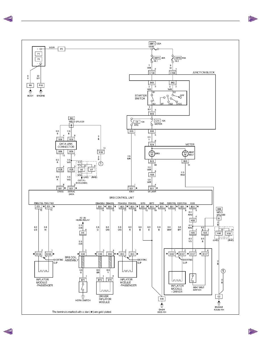
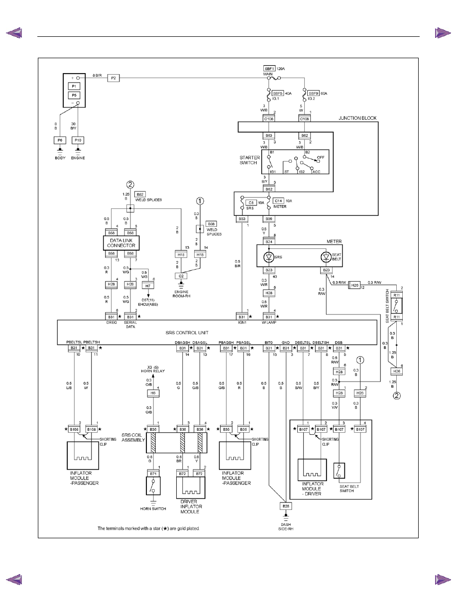
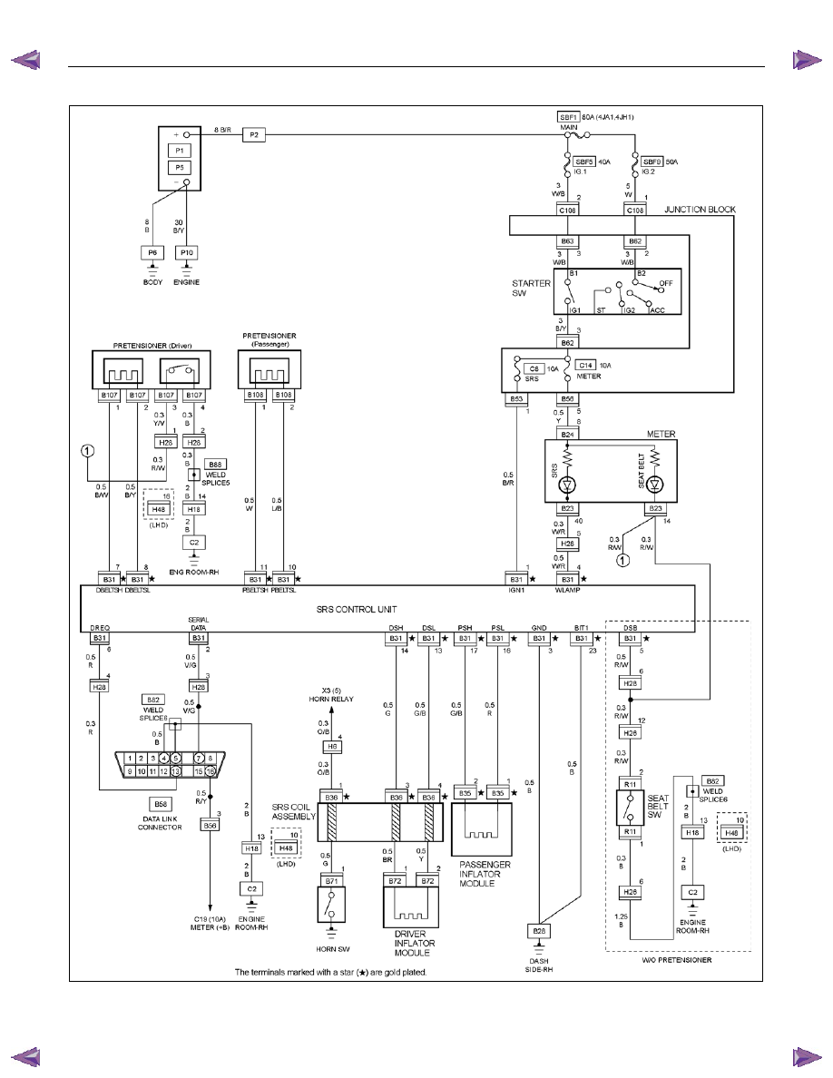
Circuit Diagram
4JJ1-TC, 4JK1-TC (Except South Africa)
RTW78AXF028601
SUPPLEMENTAL RESTRAINT SYSTEM 9A-7
4JJ1-TC (South Africa)
RTW78AXF018601
9A-8 SUPPLEMENTAL RESTRAINT SYSTEM
4JH1-TC, 4JA1-L
RTW78AXF009801
Нет комментариевНе стесняйтесь поделиться с нами вашим ценным мнением.
Текст