Isuzu KB P190. Manual — part 372

6A-128 ENGINE MECHANICAL (4JK1/4JJ1)
Reassembly
1. Install the crank angle sensor rotor.
• Attach by making a rotor tooth’s running out
side into a front side.
• Apply Loctite #262 or the equivalent to the bolt
threads (if a new bolt is used, Loctite
application is not required).
Tightening torque: 12 N
⋅⋅⋅⋅m (1.2 kg⋅⋅⋅⋅m / 104 lb in)
RTW76ASH001601
Legend
1. Crank Angle Sensor Rotor
2. Pin
Inspection
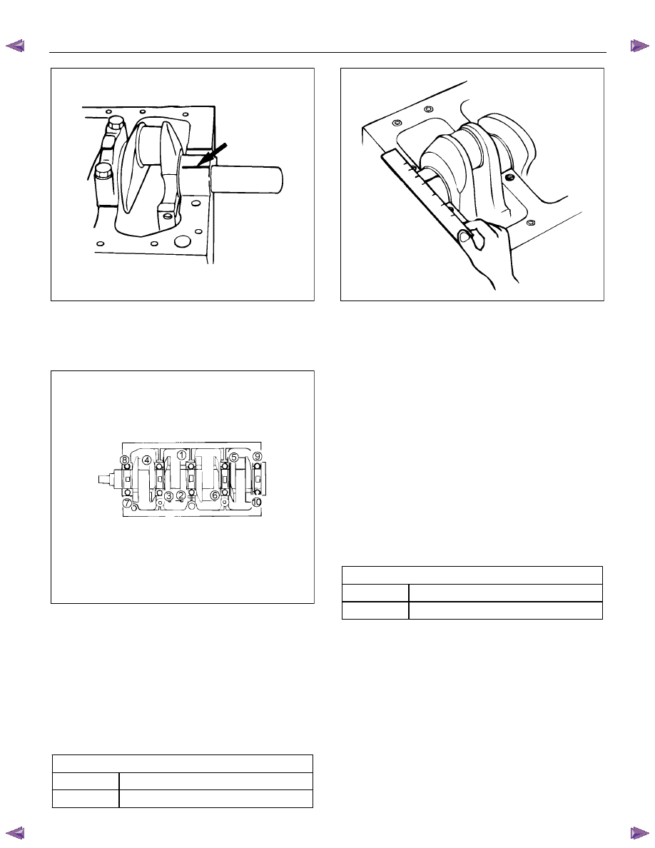
1. Thrust clearance
• Measure the crankshaft end play at the center
journal of the crankshaft.
• Do this before removing the crankshaft bearing
caps. If the measured value exceeds the
specified limit, the crankshaft thrust bearing
must be replaced.
Axial play of the crankshaft
mm (in)
Standard 0.10
(0.004)
Limit 0.30
(0.012)
Note:
Measure the thrust clearance before dismounting.
015RY00002
2. Main bearing clearance
• Remove the crank case.
Set out disassembled main bearings in the
order of the numbers.
• Remove the crankshaft. Remove the main
bearings.
• Clean the crankshaft journal and upper and
lower bearings.
• Check the bearings for damage or excessive
wear.
If you find damage or excessive wear, replace
the bearings in pairs.
• Place the upper bearings and the crankshaft on
the cylinder block. Install the crankshaft so that
it is horizontal.
Note:
Turn the crankshaft about 30 degrees to allow the
bearings to settle in.
• Place plastigage on the crankshaft journal as
shown.
• Place the lower bearings at original positions on
the bearing cap.
ENGINE MECHANICAL (4JK1/4JJ1) 6A-129
015RY00012
• Install the bearing cap and tighten bolts to the
specified tightening torque.
• Tighten the bearing cap in the sequence shown
using a torque wrench and an angle gauge.
015LX129
Tightening torque: 166 N
⋅⋅⋅⋅m (16.9 kg⋅⋅⋅⋅m / 122 lb ft)
Note:
Do not turn the crankshaft after you have tightened the
bearing cap.
• Loosen the bolts and gently remove the bearing
cap.
• Measure the widest part of the Plastigage
flattened by tightening the bearing cap to
determine the clearance.
Journal oil clearance
mm (in)
Standard
0.032 - 0.077 (0.0013 - 0.0030)
Limit 0.11
(0.0043)
LNW21BSH024401
• If the journal oil clearance exceeds the limit,
replace the main bearings altogether or the
crankshaft.
• Remove the Plastigage from the bearings and
the crankshaft.
Inspection of the crankshaft
• Check the crankshaft journal and crank pin
surfaces for wear and damage. Check the oil
seal contact surface for excessive wear and
damage.
• Check the oil port for clogging.
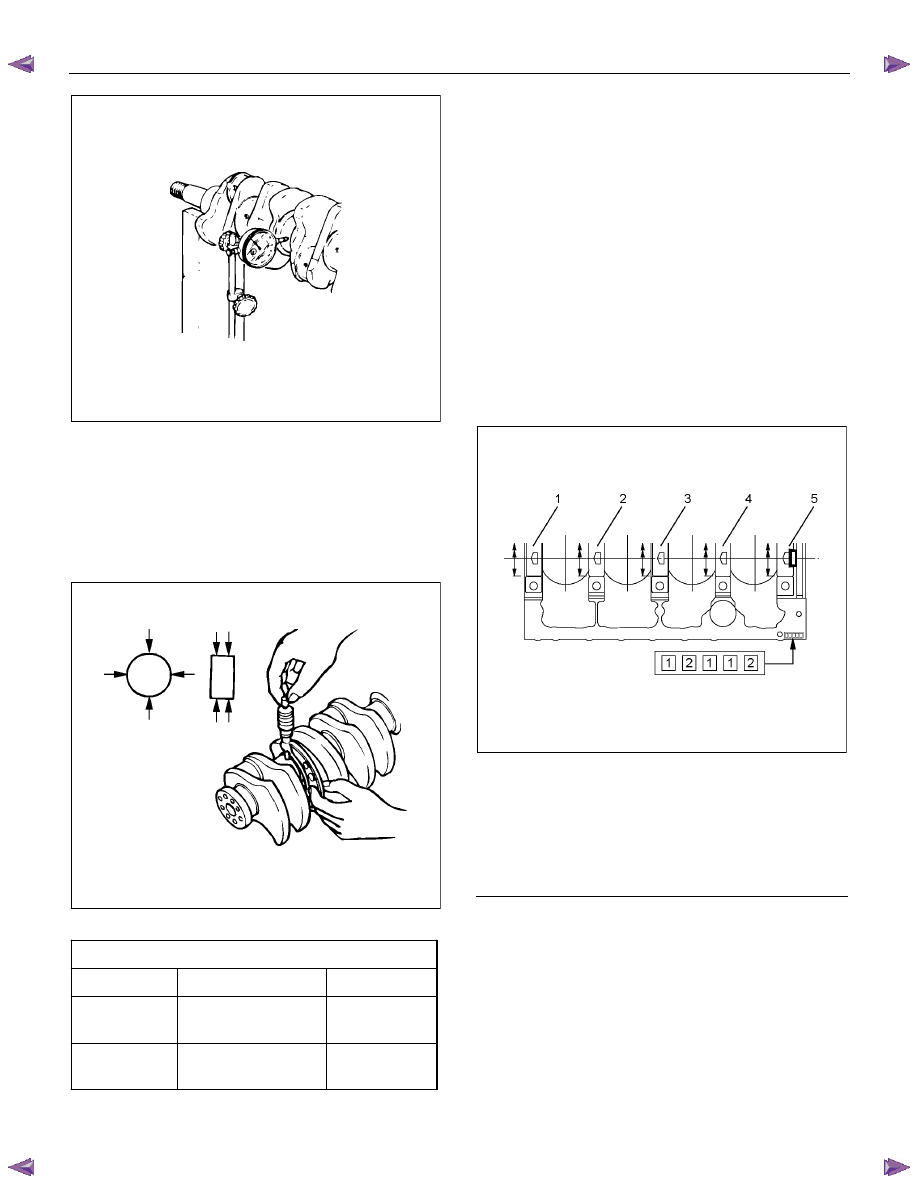
3. Crankshaft run-out
Carefully set the crankshaft on the V block. Slowly
turn the crankshaft to measure the run-out. If the
crankshaft run-out exceeds the limit, replace the
crankshaft.
Crankshaft run-out
mm (in)
Standard
0.05 or less (0.0020 or less)
Limit 0.08
(0.003)
6A-130 ENGINE MECHANICAL (4JK1/4JJ1)
015LX061
4. Measure the journal and the crankpin diameters
and uneven wear.
• Measure outer diameters of the journal and the
pin and calculate differences between the
maximum and the minimum values. Take
measurements at four positions for both the
journal and the pin.
LNW21BSH024601
Crankshaft outside diameter
mm (in)
Standard
Limit
Journal
69.917 – 69.932
(2.7526 – 2.7532)
69.91
(2.7524)
Pin
52.915 – 52.930
(2.0833 – 2.0839)
52.9
(2.083)
Note:
Tufftriding (soft nitriding treatment) is applied to
enhance strength of the crankshaft. Therefore, you
should not polish the surface of the crankshaft.
Crankshaft bearing selection
• Crankshaft bearing selection is based on the
measured diameters of the crankshaft journals
and the bearing inserts.
• Match the crankshaft bearing housing grade
marks and the crankshaft journal grade marks
in the table below to determine the correct
crankshaft bearing size.
• Crankshaft bearing housing grade marks 1, 2
or 3 are stamped on the rear right hand side of
the cylinder block.
RTW56ASH017101
Legend
1. No.1
2. No.2
3. No.3
4. No.4
5. No.5
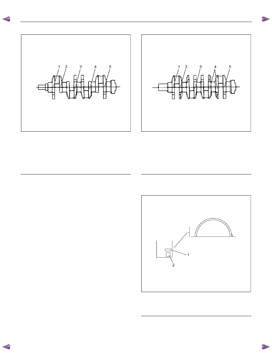
• The crankshaft journal grade marks (1 or -, 2 or
--, 3 or ---) are stamped on each crankshaft
journal web.
The crankshaft journal and bearing clearance
must be the same for each position after
installation of the crankshaft and the crankshaft
bearings.
ENGINE MECHANICAL (4JK1/4JJ1) 6A-131
4JK1
RTW56ASH023901
Legend
1. No.1
2. No.2
3. No.3
4. No.4
5. No.5
NOTE:
The crankshaft journal mark No. 4 is stamped on
crankshaft No. 4 journal web front side or rear side.
4JJ1
RTW56ASH017201
Legend
1. No.1
2. No.2
3. No.3
4. No.4
5. No.5
Note:
Be careful about difference in the shape of the bearings
when installing them.
RTW56ASH017301
Legend
1. Lot
No.
2. Size
Code
Нет комментариевНе стесняйтесь поделиться с нами вашим ценным мнением.
Текст