Isuzu KB P190. Manual — part 948
Automatic Transmission – 4L60E – Electrical Diagnosis
Page 7C2–6
DTC Description. . . . . . . . . . . . . . . . . . . . . . . . . . . . . . . . . . . . . 100
Circuit Description. . . . . . . . . . . . . . . . . . . . . . . . . . . . . . . . . . . . 100
Conditions for Running the DTC . . . . . . . . . . . . . . . . . . . . . . . . . . . . . .. 101
Conditions for Setting the DTC. . . . . . . . . . . . . . . . . . . . . . . . . . . . . . . 101
Action Taken When the DTC Sets . . . . . . . . . . . . . . . . . . . . . . . . . . . . . 101
Conditions for Clearing the DTC . . . . . . . . . . . . . . . . . . . . . . . . . . . . . .. 101
Test Description. . . . . . . . . . . . . . . . . . . . . . . . . . . . . . . . . . . . . 101
DTC P0977 Diagnostic Table. . . . . . . . . . . . . . . . . . . . . . . . . . . . . . . . 101
4.32
DTC P1810, P1815 and P1816 – Transmission Fluid Pressure Position Switch. . . . . . . . . . ... 103
DTC Description. . . . . . . . . . . . . . . . . . . . . . . . . . . . . . . . . . . . . 103
Circuit Description. . . . . . . . . . . . . . . . . . . . . . . . . . . . . . . . . . . . 103
Conditions for Running the DTC . . . . . . . . . . . . . . . . . . . . . . . . . . . . . .. 104
DTC P1810 . . . . . . . . . . . . . . . . . . . . . . . . . . . . . . . . . . . . . 104
DTC P1815 . . . . . . . . . . . . . . . . . . . . . . . . . . . . . . . . . . . . . 104
DTC P1816 . . . . . . . . . . . . . . . . . . . . . . . . . . . . . . . . . . . . . 104
Conditions for Setting the DTC. . . . . . . . . . . . . . . . . . . . . . . . . . . . . . . 104
DTC P1810 . . . . . . . . . . . . . . . . . . . . . . . . . . . . . . . . . . . . . 104
DTC P1815 . . . . . . . . . . . . . . . . . . . . . . . . . . . . . . . . . . . . . 104
DTC P1816 . . . . . . . . . . . . . . . . . . . . . . . . . . . . . . . . . . . . . 104
Action Taken When the DTC Sets . . . . . . . . . . . . . . . . . . . . . . . . . . . . . 104
Conditions for Clearing the DTC . . . . . . . . . . . . . . . . . . . . . . . . . . . . . .. 105
Diagnostic Aids. . . . . . . . . . . . . . . . . . . . . . . . . . . . . . . . . . . . .. 105
Test Description. . . . . . . . . . . . . . . . . . . . . . . . . . . . . . . . . . . . . 105
DTC P1810, P1815 and P1816 Diagnostic Table. . . . . . . . . . . . . . . . . . . . . . . .. 105
4.33
DTC Description. . . . . . . . . . . . . . . . . . . . . . . . . . . . . . . . . . . . . 108
Circuit Description. . . . . . . . . . . . . . . . . . . . . . . . . . . . . . . . . . . . 108
Conditions for Running the DTC . . . . . . . . . . . . . . . . . . . . . . . . . . . . . .. 108
Conditions for Setting the DTC. . . . . . . . . . . . . . . . . . . . . . . . . . . . . . . 108
Action Taken When the DTC Sets . . . . . . . . . . . . . . . . . . . . . . . . . . . . . 108
Conditions for Clearing the DTC . . . . . . . . . . . . . . . . . . . . . . . . . . . . . .. 108
Test Description. . . . . . . . . . . . . . . . . . . . . . . . . . . . . . . . . . . . . 109
DTC P2763 Diagnostic Table. . . . . . . . . . . . . . . . . . . . . . . . . . . . . . . . 109
4.34
DTC Description. . . . . . . . . . . . . . . . . . . . . . . . . . . . . . . . . . . . . 111
Circuit Description. . . . . . . . . . . . . . . . . . . . . . . . . . . . . . . . . . . . 111
Conditions for Running the DTC . . . . . . . . . . . . . . . . . . . . . . . . . . . . . .. 111
Conditions for Setting the DTC. . . . . . . . . . . . . . . . . . . . . . . . . . . . . . . 111
Action Taken When the DTC Sets . . . . . . . . . . . . . . . . . . . . . . . . . . . . . 111
Conditions for Clearing the DTC . . . . . . . . . . . . . . . . . . . . . . . . . . . . . .. 111
Test Description. . . . . . . . . . . . . . . . . . . . . . . . . . . . . . . . . . . . . 112
DTC P2764 Diagnostic Table. . . . . . . . . . . . . . . . . . . . . . . . . . . . . . . . 112
4.35
DTC Description. . . . . . . . . . . . . . . . . . . . . . . . . . . . . . . . . . . . . 115
Circuit Description. . . . . . . . . . . . . . . . . . . . . . . . . . . . . . . . . . . . 115
Conditions for Running the DTC . . . . . . . . . . . . . . . . . . . . . . . . . . . . . .. 115
Conditions for Setting the DTC. . . . . . . . . . . . . . . . . . . . . . . . . . . . . . . 115
Action Taken When the DTC Sets . . . . . . . . . . . . . . . . . . . . . . . . . . . . . 115
Conditions for Clearing the DTC . . . . . . . . . . . . . . . . . . . . . . . . . . . . . .. 116
Diagnostic Aids. . . . . . . . . . . . . . . . . . . . . . . . . . . . . . . . . . . . .. 116
Test Description. . . . . . . . . . . . . . . . . . . . . . . . . . . . . . . . . . . . . 116
DTC P2769 Diagnostic Table. . . . . . . . . . . . . . . . . . . . . . . . . . . . . . . . 116
4.36
DTC Description. . . . . . . . . . . . . . . . . . . . . . . . . . . . . . . . . . . . . 119
Circuit Description. . . . . . . . . . . . . . . . . . . . . . . . . . . . . . . . . . . . 119
Conditions for Running the DTC . . . . . . . . . . . . . . . . . . . . . . . . . . . . . .. 119
Conditions for Setting the DTC. . . . . . . . . . . . . . . . . . . . . . . . . . . . . . . 119
Action Taken When the DTC Sets . . . . . . . . . . . . . . . . . . . . . . . . . . . . . 120
Conditions for Clearing the DTC . . . . . . . . . . . . . . . . . . . . . . . . . . . . . .. 120
Test Description. . . . . . . . . . . . . . . . . . . . . . . . . . . . . . . . . . . . . 120
Automatic Transmission – 4L60E – Electrical Diagnosis
Page 7C2–7
DTC P2770 Diagnostic Table. . . . . . . . . . . . . . . . . . . . . . . . . . . . . . . . 120
4.37
DTC U0073 and U0100 – CAN-Bus No Communication With ECM (Engine Control Module). . . . . .. 121
DTC Description. . . . . . . . . . . . . . . . . . . . . . . . . . . . . . . . . . . . . 121
Circuit Description. . . . . . . . . . . . . . . . . . . . . . . . . . . . . . . . . . . . 121
Conditions for Running the DTC . . . . . . . . . . . . . . . . . . . . . . . . . . . . . .. 121
Conditions for Setting the DTC. . . . . . . . . . . . . . . . . . . . . . . . . . . . . . . 121
DTC U0073 . . . . . . . . . . . . . . . . . . . . . . . . . . . . . . . . . . . . . 121
DTC U0100 . . . . . . . . . . . . . . . . . . . . . . . . . . . . . . . . . . . . . 121
Action Taken When the DTC Sets . . . . . . . . . . . . . . . . . . . . . . . . . . . . . 122
Conditions for Clearing the DTC . . . . . . . . . . . . . . . . . . . . . . . . . . . . . .. 122
Test Description. . . . . . . . . . . . . . . . . . . . . . . . . . . . . . . . . . . . . 122
DTC P0864 and U0101 Diagnostic Table. . . . . . . . . . . . . . . . . . . . . . . . . . .. 122
5
Electrical Specifications . . . . . . . . . . . . . . . . . . . . . . . . . . . . . 124
5.1
Transmission Fluid Temperature (TFT) Sensor Specifications . . . . . . . . . . . . . . . . . . 124
5.2
Range Reference. . . . . . . . . . . . . . . . . . . . . . . . . . . . . . . . . . . . 124
5.3
Transmission Fluid Pressure Manual Valve Position Switch Logic . . . . . . . . . . . . . . . .. 125
5.4
Transmission Range Switch Logic. . . . . . . . . . . . . . . . . . . . . . . . . . . . ... 125
5.5
Component Resistance . . . . . . . . . . . . . . . . . . . . . . . . . . . . . . . . . . 126
5.6
Shift Solenoid Valve State and Gear Ratio . . . . . . . . . . . . . . . . . . . . . . . . . .. 126
5.7
Line Pressure . . . . . . . . . . . . . . . . . . . . . . . . . . . . . . . . . . . . . . 126
6
Special Tools . . . . . . . . . . . . . . . . . . . . . . . . . . . . . . . . . ..127
Automatic Transmission – 4L60E – Electrical Diagnosis
Page 7C2–8
1 General
Information
1.1 Introduction
This Section covers the electrical diagnostic for the 4L60E automatic transmission when mated to a V6 engine.
1.2 General
Description
The 4L60E automatic transmission incorporates electronic controls that utilise a transmission control module (TCM) to
control shift points through:
•
the 1-2 and 2-3 shift solenoid valves,
•
the 3-2 downshift solenoid valve,
•
a torque converter clutch (TCC) solenoid valve,
•
apply and release through the TCC pulse width modulated (PWM) solenoid valve, and
•
line pressure through the pressure control (PC) solenoid valve.
Electrical signals from various sensors provide information to the TCM about the following:
•
vehicle speed,
•
throttle position,
•
engine coolant temperature,
•
transmission fluid temperature,
•
gear range selector position,
•
engine speed,
•
converter turbine speed, and
•
engine load braking and operating mode.
The TCM uses this information to determine the precise moment to upshift or downshift, apply or release the TCC and
what fluid pressure is needed to apply the clutches. This type of control provides consistent and precise shift points and
shift quality based on the operating conditions of the vehicle.
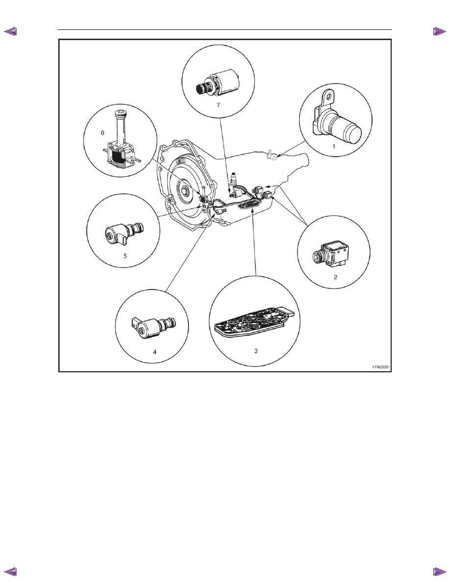
Figure 7C2 – 1 shows the location of the internal electronic components in the transmission.
Automatic Transmission – 4L60E – Electrical Diagnosis
Page 7C2–9
Figure 7C2 – 1
Legend
1
Vehicle Speed Sensor
5
Torque Converter Clutch Pulse Width Modulation (TCC
PWM) Solenoid Valve
2
1-2 Shift Solenoid (Solenoid A) and 2-3 Shift Solenoid
(Solenoid B)
6
Torque Converter Clutch (TCC) Solenoid Valve
3
Automatic Transmission Fluid Pressure (TFP) Manual Valve
Position
7
Pressure Control (PC) Solenoid Valve
4
3-2 Downshift Solenoid
Transmission Adaptive Functions
The 4L60E automatic transmission uses a line pressure control system, which has the ability to adapt the system line
pressure to compensate for normal wear within the transmission, such as the clutch pack fibre plates, seals, springs, etc.
The adapt feature is similar in function to the long term/short term fuel trim feature of the engine management system.
The 4L60E automatic transmission uses the adapt function for garage shifts, upshifts and torque converter clutch (TCC)
application. The TCM monitors the engine torque to determine if the shift is occurring too fast or too slow and adjusts the
pressure control solenoid to maintain the correct shift feel.
Нет комментариевНе стесняйтесь поделиться с нами вашим ценным мнением.
Текст