Isuzu KB P190. Manual — part 714
Engine Mechanical – V6
Page 6A1–79
Page 6A1–79
8
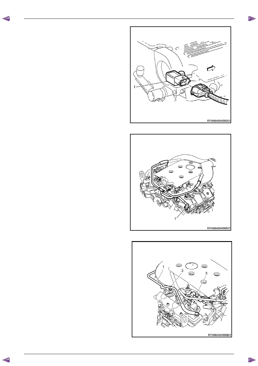
Disconnect the wiring harness connector from the
barometric (BARO) pressure sensor (1).
Figure 6A1 – 37
9
Disconnect the PCV tube connector (1) from the
upper intake manifold assembly.
Figure 6A1 – 38
10
Remove the bolt (3) attaching the EVAP valve and the
fuel injector wiring harness connector mounting
bracket to the upper intake manifold assembly.
11
Move the EVAP valve and the fuel injector wiring
harness connector mounting bracket clear of the upper
intake manifold assembly.
12
Disconnect the PCV fresh air tube (1) from its upper
intake manifold mounting clip (2).
Figure 6A1 – 39
Engine Mechanical – V6
Page 6A1–80
Page 6A1–80
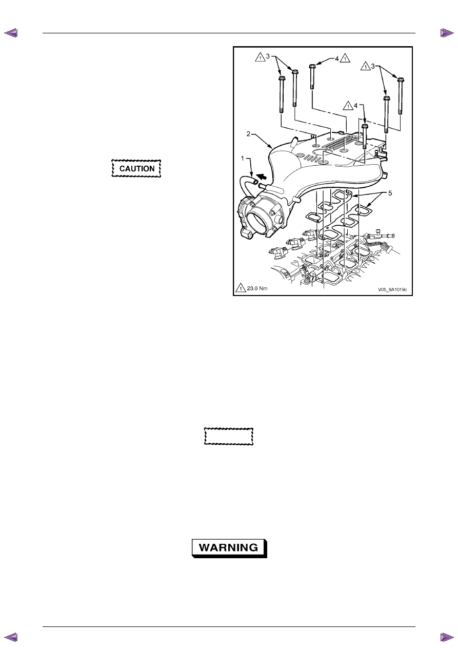
13
Disconnect the EVAP valve outlet tube (1) from the
intake manifold (2).
14
Remove the four long (3) (165 mm long) and two short
bolts (4) (70 mm long) attaching the upper intake
manifold (2) to the cylinder heads and lower intake
manifold.
15
Lift the upper intake manifold (2) clear from the lower
half and then remove the upper intake manifold from
the engine.
16
Remove and discard the upper to lower intake
manifold gaskets (5).
• When the upper intake manifold is
removed, plug each of the lower intake
runner openings with lint free cloth, to
stop the entry of foreign material into the
engine.
• Do not reuse the upper to lower intake
manifold gaskets (5).
Figure 6A1 – 40
17
Remove the upper and lower intake manifold assembly from the engine.
18
Remove lower intake manifold to cylinder head gasket.
Disassemble
Remove the following from the upper intake manifold, refer to
Section 6C1-3 Engine Management – V6 – Service
Operations
:
•
BARO sensor and
•
Throttle body assembly.
Clean
CAUTION
Due to the aluminium alloy construction of
the intake manifold, wire brushes and steel
scrapers must not be used during the
cleaning process, as damage to sealing
surfaces may occur. Use of a wooden or
plastic scraper is preferred.
1
Clean mating surfaces ensuring any gasket material is removed.
2
Clean the manifold using a suitable solvent.
Safety glasses must be worn when using
compressed air.
3
Dry the timing components with compressed air.
Engine Mechanical – V6
Page 6A1–81
Page 6A1–81
Inspect
1
Inspect the intake manifold for the following fault conditions:
•
Damaged sealing and mating surfaces.
•
Damaged lower intake manifold gasket.
•
Damage or excessive debris on the threaded and through holes.
•
Cracks or damage to the intake manifold body.
N O T E
If the lower intake manifold is cracked or
damaged, it must be replaced. No welding or
patching of the intake manifold should be
performed.
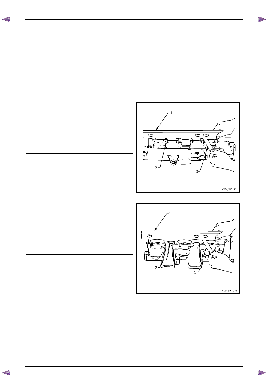
2
Place a straight edge (1) across the upper intake
manifold sealing surface (2).
3
Using a feeler gauge (3), measure the clearance
between the manifold and the straight edge.
4
If the clearance between the upper intake manifold
sealing surface and the straight edge exceeds the
specified maximum warpage, replace the manifold.
Upper manifold maximum
warpage . . . . . . . . . . . . . . . 0.05 mm
Figure 6A1 – 41
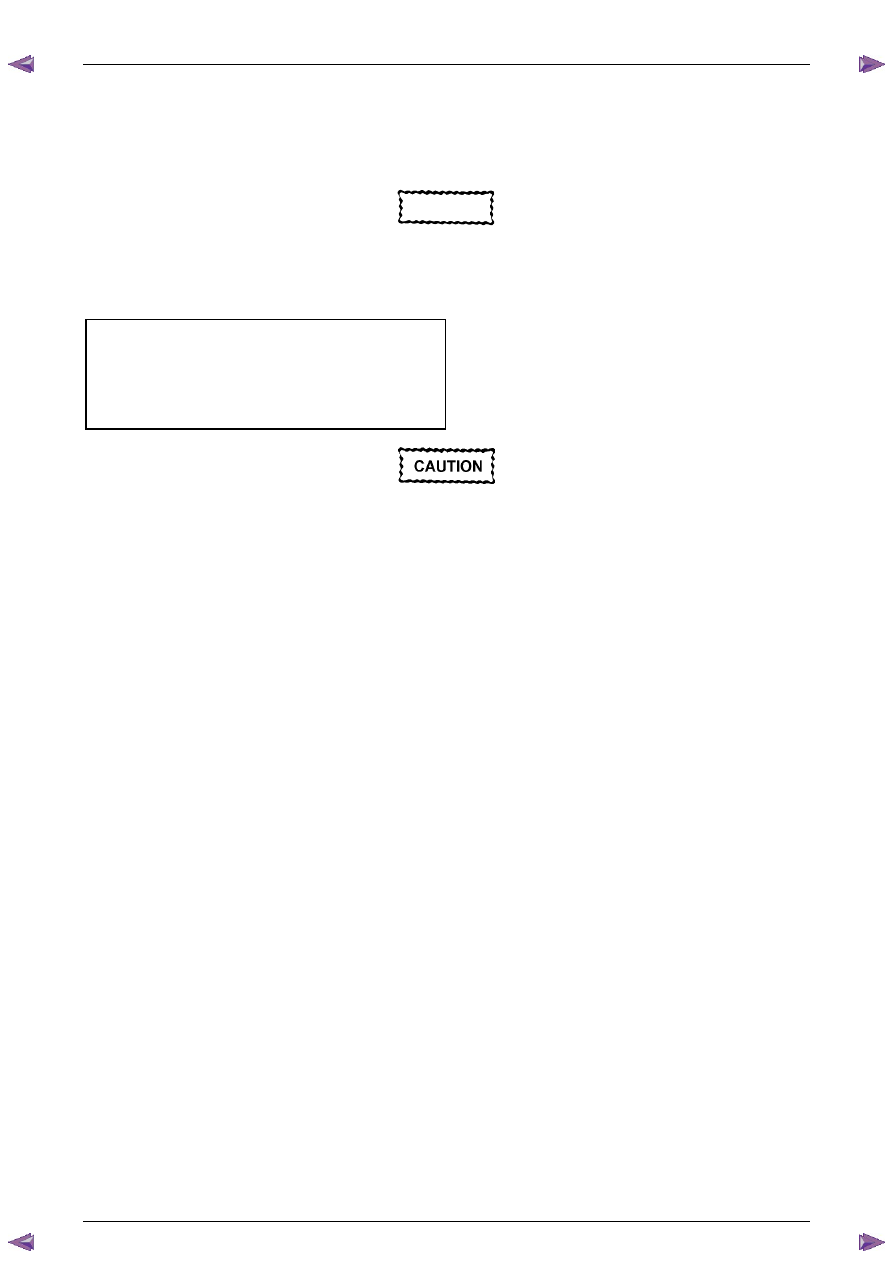
5
Place a straight edge (1) across the lower intake
manifold sealing surface (2).
6
Using a feeler gauge (3), measure the clearance
between the manifold and the straight edge.
7
If the clearance between the lower intake manifold
sealing surface and the straight edge exceeds the
specified maximum warpage, replace the manifold.
Lower manifold maximum
warpage . . . . . . . . . . . . . . . 0.05 mm
Figure 6A1 – 42
Reassemble
Reassembly of the upper manifold is the reverse of the disassembly procedure .
Engine Mechanical – V6
Page 6A1–82
Page 6A1–82
Reinstall
Reinstallation of the upper intake manifold and the upper and lower intake manifold assembly is the reverse of the
removal procedure, noting the following:
1
Only new gaskets are to be fitted between the upper and lower intake manifolds.
CAUTION
Tighten the intake manifold bolts in a circular
pattern starting at the centre bolt and moving
outward.
2
Ensure that all fasteners are tightened to the correct torque specification.
Upper intake manifold to lower
intake manifold attaching bolt
torque specification . . . . . . . . . . . 23.0 Nm
Upper intake manifold to
cylinder head attaching bolt
torque specification . . . . . . . . . . . 23.0 Nm
Incorrect wiring connector installation may
cause component malfunction or component
damage.
3
Ensure all wiring connectors are fully engaged and if applicable, locked in place.
4
Ensure all wiring harnesses are correctly routed and attached securely in their retaining clips.
5
Ensure that all hoses and pipes are routed correctly and that any retaining clips are correctly installed.
6
Start and run the engine to check for correct operation.
Нет комментариевНе стесняйтесь поделиться с нами вашим ценным мнением.
Текст