Isuzu KB P190. Manual — part 115
4B-16 REAR AXLE
φφφφ220mm
Torque : Bolt
64 N
⋅m (6.5 kgf⋅m/47 lb⋅ft)
Nut 44
N
⋅m (4.5 kgf⋅m/33 lb⋅ft)
φφφφ194mm
Torque : Bolt
25 N
⋅m (2.5 kgf⋅m/18 lb⋅ft)
Nut 37
N
⋅m (3.8 kgf⋅m/27 lb⋅ft)
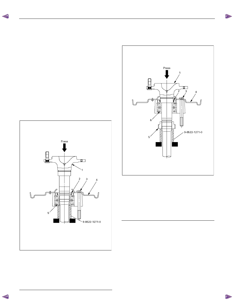
5. Axle Shaft Assembly
a. Insert new double taper roller bearing in the
bearing holder with oil seal.
b. Set special tool (support stand : 9-8522-1271-
0) on a bench press.
c. Put bearing holder with bearing and oil seal
and back plate on the support stand as
following illustration.
d. Insert bolts and axle shaft, aligning center of
holes.
e. Press fit axle shaft into double taper roller
bearing.
420R300010
Legend
1. Axle shaft
2. Oil Seal
3. Bolt
4. Back Plate
5. Double Taper Roller Bearing
6. Put new retainer on the special tool 9-8522-1271-
0.
7. Press fit axle shaft with the bearing into retainer
and make axle shaft assembly.
420R300011
Legend
1. Axle shaft
2. Oil Seal
3. Bolt
4. Back Plate
5. Retainer
6. Double Taper Roller Bearing
REAR AXLE 4B-17
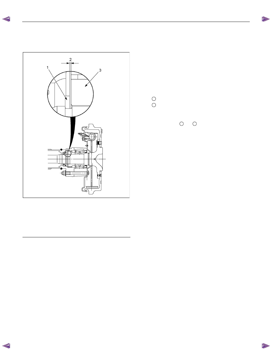
8. Certainly install new snap ring, use snap ring
pliers. When transform or damage, replace new
one.
RTW34BMH000101
Legend
1. Snap ring
2. Crevice
3. Retainer (with ABS)
Retainer (without ABS)
9. Insert a shim of sufficient thickness between
snap ring and end of retainer.
Standard 0
− 0.2 mm (0 − 0.008 in)
Crevice is measured using thickness gauge, and
when crevice exceeds 0.2 mm (0.008 in), it
adjusts so that is may become 0.2 mm (0.008 in)
or less using shim.
Shim Pats No.
Thickness
1
9-41519110-
∗ 0.18 mm (0.0071 in)
2
8-97130387-
∗ 0.50 mm (0.0197 in)
Crevice
No. of shim
Total
mm
(in)
1
2
mm
(in)
1.0(0.0394)
2
1.00(0.0394)
0.9(0.0354) 2
1
0.86(0.0339)
0.8(0.0315) 1
1
0.68(0.0268)
0.7(0.0276) 1
1
0.68(0.0268)
0.6(0.0236)
1
0.50(0.0197)
0.5(0.0197)
1
0.50(0.0197)
0.4(0.0157) 2
0.36(0.0142)
0.3(0.0118) 1
0.18(0.0071)
0.2(0.0079) 1
0.18(0.0071)
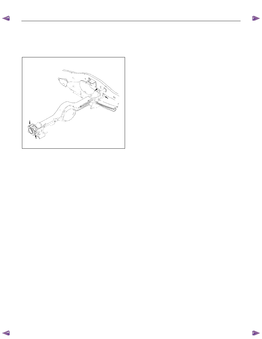
10.
Install axle shaft assembly in rear axle case
assembly.
a. Clean the mating surface of axle case and
bearing holder.
b.
Apply Three Bond 1215 (TB1215) or
equivalent on the surface of axle case
assembly.
Note:
When inserting an axle shaft, it inserts so that an
oil seal may not be damaged.
11. Install and tighten bearing holder fixing nut to the
specified torque.
Torque : 84 N
⋅m (8.6 kgf⋅m/62 lb⋅ft)
12. Install wheel cylinder and tighten the bolt to the
specified torque.
Torque : 9 N
⋅m (0.9 kgf⋅m/78 lb⋅in)
13.
Install parking brake outer cable in back plate
and inner cable in parking brake lever.

4B-18 REAR AXLE
14. Install shoe assembly with adjuster lever, shoe
assembly with parking brake lever and spring.
15. Install return spring.
16. Install shoe clamp spring and tension pin.
305R300001
Legend
1. Tension Pin
2. Shoe Clamp Spring
3. Return Spring
4. Shoe Assembly with Parking Brake Lever
5. Shoe Assembly with Adjuster Lever
6. Spring
7. Parking Brake Cable
8. Adjuster
9. Parking Brake Lever
10. Adjuster Spring
11. Adjuster Lever
12. Wheel Cylinder
13. Back plate
REAR AXLE 4B-19
17. Install brake pipe and ABS sensor and tighten it
to the specified torque.
Torque
:
ABS Sensor
8 N
⋅m (0.8 kgf⋅m/69 lb⋅in)
Brake Pipe
16 N
⋅m (1.6 kgf⋅m/12 lb⋅ft)
420R30003
18. Bleed brake pipe at the wheel cylinder. (Refer to
the section “Power-assisted Brake System”)
19. Install brake drum.
• Install propeller shaft. (Refer to Section “Rear
Propeller Shaft”.)
• Refill differential oil.
• Install wheel and tire.
• Lower vehicle.
Нет комментариевНе стесняйтесь поделиться с нами вашим ценным мнением.
Текст