Isuzu KB P190. Manual — part 400
6D-12 ENGINE ELECTRICAL (4JK1/4JJ1)
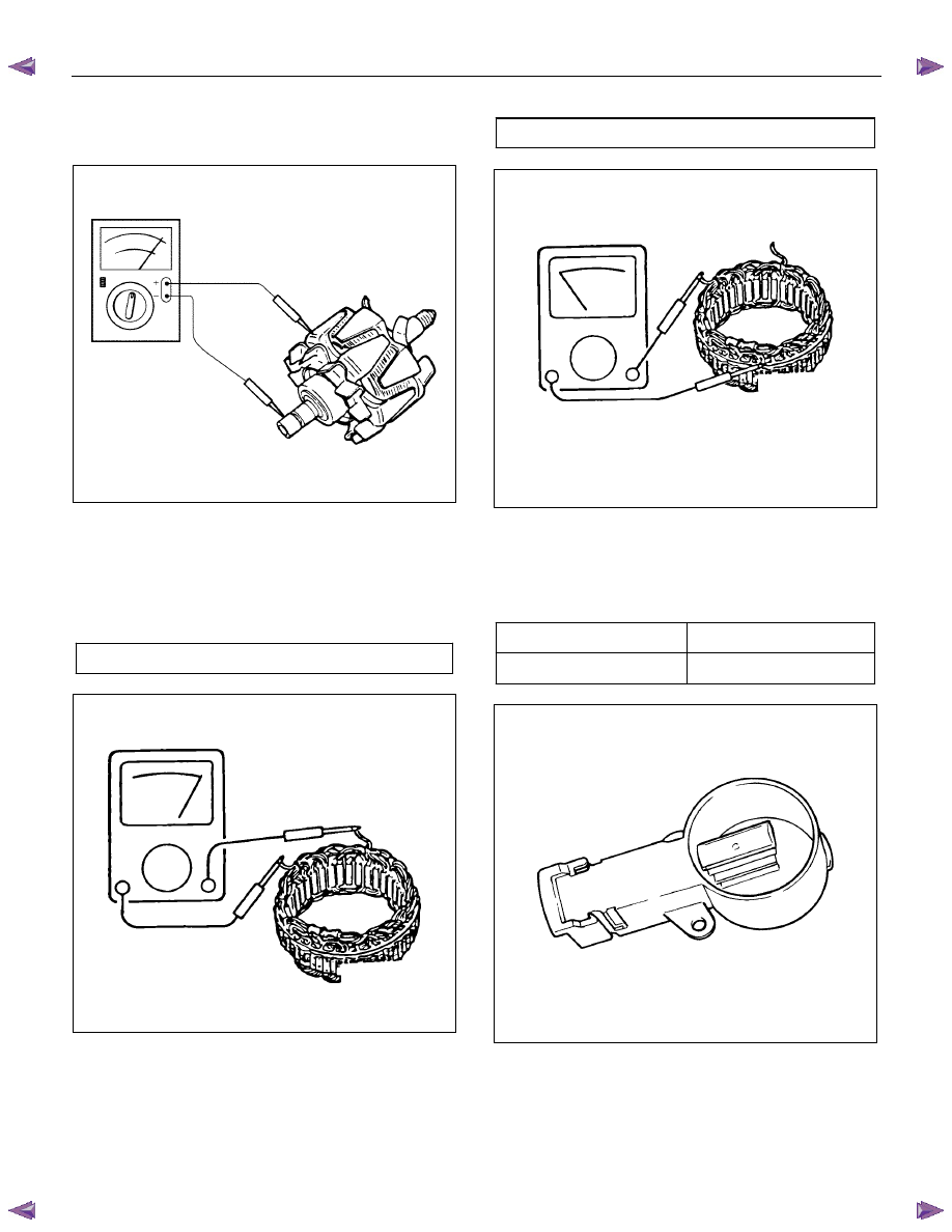
4. Check for conductivity between the slip rings and
the rotor core. If there is continuity, the rotor
assembly must be replaced.
066RS017
Stator Coil
1.
Measure the stator coil resistance. If the
resistance is less than the specified value, the
stator coil must be replaced.
Stator coil resistance
0.07
Ω at 20°C (68°F)
066RS034
2. Measure the resistance between the stator coil
and the stator core. If the resistance is less than
the specified value, the stator coil must be
replaced.
Stator coil/core resistance
M
Ω
1
066RS035
Brushes
Measure the brush height. If the height is less than the
specified limit, the brushes must be replaced.
Brush height
mm (in)
Standard 18
(0.709)
Limit 5.5
(0.217)
066RW024
ENGINE ELECTRICAL (4JK1/4JJ1) 6D-13
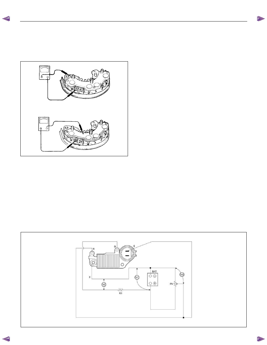
Rectifier
Measure each of the diode resistances in both
directions (anode/cathode and cathode/anode). If any of
the diodes have the same resistance in both directions,
the rectifier must be replaced.
066RS036
Regulator Assembly
There are 3 checkpoints (12V batteries, 10 ohms 3W
resistor, 0-50V/0.5V steps, and 300 ohms 12W variable
resistor). Refer to the schematic below.
Measuring Procedure
1. Measure the voltage (BAT) at the V1 checkpoint. A
10-13 volt reading indicates that the BAT battery is
good.
2. Measure the voltage at checkpoints V1 and V2 as
you gradually increase the resistance of the
variable resistor from 0. The voltage at V1 should
change with the voltage at V2. If it does not, the
regulator is damaged and must be replaced.
3. Measure the voltage at checkpoint V3 with the
variable resistor setting fixed. If the measured
voltage is 14.4 ± 0.3, the regulator is good. If the
measured voltage is outside this range, the
regulator is damaged and must be replaced.
RTW56DMF000301
6D-14 ENGINE ELECTRICAL (4JK1/4JJ1)
Reassembly
Follow the disassembly steps in reverse order to
reassemble the generator. Pay close attention to the
items below.
• Be very careful not to reverse battery polarity.
Reversed battery polarity will destroy the rectifier
diodes.
• Do not ground the generator B-terminal. Heat and
fire damage to the harness will result.
• If using a fast charge procedure, be sure to
disconnect the battery positive cable. If you do not,
the rectifier diodes will be exposed to high positive
voltage that will destroy them.
• Be very careful to reassemble the parts to their
original positions. Particular care must be taken
with insulated parts.
• Carefully clean all insulated parts so that they are
completely free of oil and/or grease.
• Be sure that B-terminal twist-type stoppers (round
terminal) are securely inserted before tightening
the nuts.
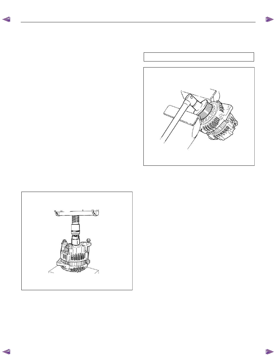
Final Assembly
1. Use a bench press to install the rotor and rear
cover to the front cover.
RTW56DSH000201
2. Install the pulley to the rotor shaft and tighten the
bolt to the specified torque.
Pulley bolt torque
N
⋅m (kg⋅m / lb ft)
111 (11.3 / 81.7)
RTW56DSH000101
ENGINE ELECTRICAL (4JK1/4JJ1) 6D-15
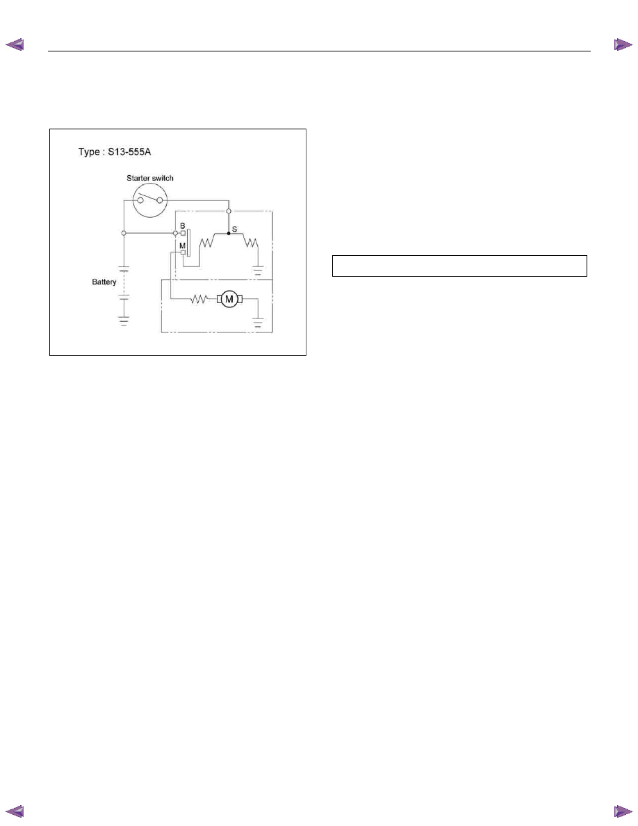
Starter Motor
Starting Circuit Diagram
RTW46DSH005501
Removal and Installation
Read this Section carefully before performing any
removal and installation procedure. This Section gives
you important points as well as the order of operation.
Be sure that you understand everything in this Section
before you begin.
Important Operations - Removal
Starter Motor
1. Disconnect the battery cable and the ground cable
at the battery terminals.
2. Remove the A/T oil level gage.
3. Remove the Engine oil level gage.
4. Disconnect the magnetic switch cable at the
terminal bolts.
5. Disconnect the battery cable at the starter motor
and the ground cable at the cylinder body.
6. Remove the starter motor from the engine.
Important Operations – Installation
Follow the removal procedure in the reverse order to
perform the installation procedure. Pay careful attention
to the important points during the installation procedure.
Starter Motor
1. Install the starter motor to the rear plate.
2. Tighten the starter motor bolts to the specified
torque.
Starter Motor Bolt Torque
N
⋅m (kg⋅m/lb ft)
85 (8.7 / 63)
3. Install the Engine oil level gage.
4. Install the A/T oil level gage.
5. Reconnect the battery cable at the starter motor
and the ground cable at the cylinder body.
6. Reconnect the battery cable and the ground cable
at the battery terminals.
Нет комментариевНе стесняйтесь поделиться с нами вашим ценным мнением.
Текст