Isuzu KB P190. Manual — part 1299
8A-258 ELECTRICAL-BODY AND CHASSIS
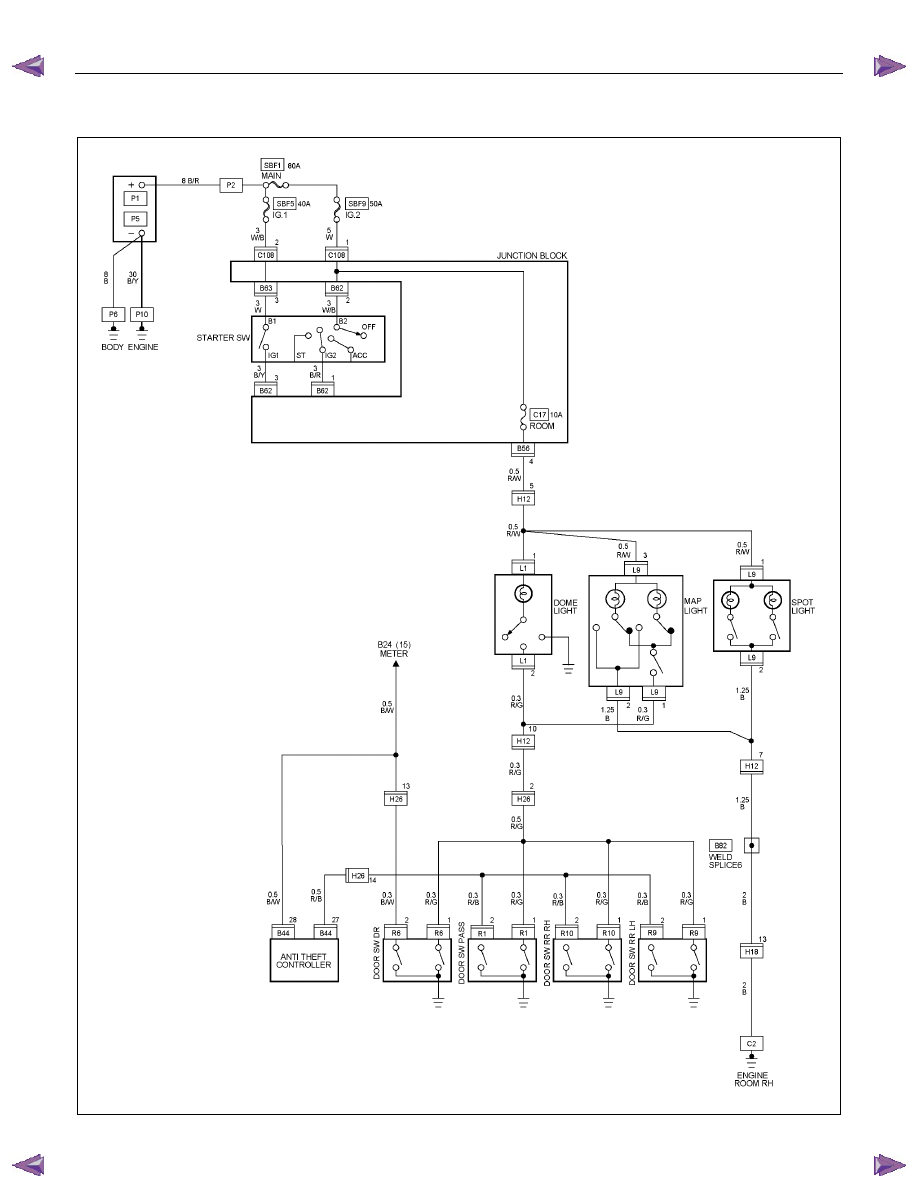
CIRCUIT DIAGRAM 4JA1T (L)
RTW78AXF005901
ELECTRICAL-BODY AND CHASSIS 8A-259
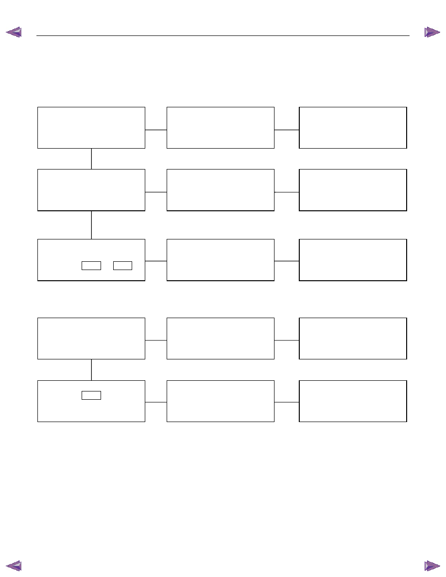
TROUBLESHOOTING
1. Dome light dose not light
Checkpoint
Trouble
Cause
Countermeasure
Replace the dome light bulb
Burned out the bulb
NG
Repair or replace the dome
light assembly
Dome light switch function
Switch malfunction
Repair open circuit or
connector contact
Continuity between
connector 5
H12
- 1
L1
Open circuit or poor connector
contact
NG
NG
OK
OK
Dome light bulb continuity
2. Dome light does not go out
Repair or replace the door
switch
Switch malfunction or foreign
material switch
NG
Repair short circuit or
connector contact
Continuity between
connector 2
L1
-ground
when shutting the door
(Should be no continuity)
Short circuit
NG
OK
Door switch function (Both
side)
8A-260 ELECTRICAL-BODY AND CHASSIS
REMOVAL AND INSTALLATION
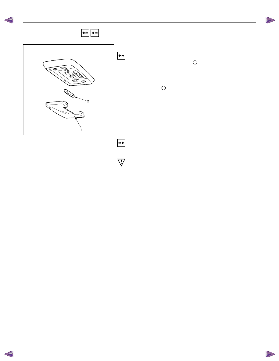
DOME LIGHT
Removal
1. Remove the dome light lens
1
free.
2. Remove two dome light fixing screws.
3. Remove the wiring connector.
4. Remove the dome light.
5. Pull the bulb
2
to remove it.
Installation
Follow the removal procedure in the reverse order to install the
dome light.
Pay close attention to the important points mentioned in the
following paragraphs.
Bulb
Be absolutely sure that the dome light bulb is correctly
installed.
This will prevent a poor contact and an open circuit.
ELECTRICAL-BODY AND CHASSIS 8A-261
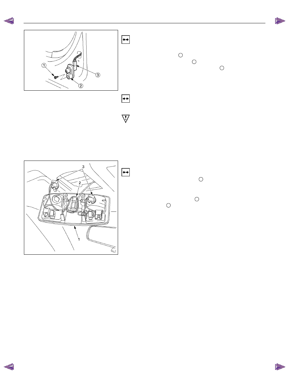
DOOR SWITCH
Removal
1. Disconnect the battery ground cable.
2. Loosen the screw
1
.
3. Remove the door switch
2
.
4. Disconnect the door switch connector
3
.
Installation
Follow the removal procedure in the reverse order to install the
spot light.
Pay close attention to the important points mentioned in the
following paragraphs.
Connector
Be absolutely sure that the door switch connector is securely
connected.
This will prevent a poor contact and an open circuit.
SPOTLIGHT (MAP Light)
Removal
1. Grasp the spotlight housing
1
with both hands.
Pull the housing straight down.
This will release the clip.
2. Disconnect the connector
2
.
3. Turn socket
3
counterclockwise to remove it.
Нет комментариевНе стесняйтесь поделиться с нами вашим ценным мнением.
Текст