Isuzu KB P190. Manual — part 158

BRAKE CONTROL SYSTEM 5A-39
Step Action Value(s)
Yes
No
3
1. Ignition “OFF”, disconnect the EHCU.
2. Check the DLC (Data Link Connector) circuit for an
open, short to ground, or short to voltage.
Also, check the DLC ignition feed circuit for an open
or short to ground and the DLC ground circuit for an
open.
3. If a problem is found, repair as necessary.
Was a problem found?
-
Go to Step 2
Go to Step 4
4
1. Check the EHCU circuit for an open, short to
ground, or short to voltage. Also, check the EHCU
ignition feed circuit for an open or short to ground
and the EHCU ground circuit for an open.
2. If a problem is found, repair as necessary.
Was a problem found?
-
Go to Step 2
Go to Step 11
5
Select “Display DTCs” with the Tech 2.
Are any DTCs stored?
-
Go to Step 6
Go to Step 10
6
Review and record for Tech 2 Failure Records data
and DTCs.
Is the action complete?
-
Go to Step 7
-
7
The DTC is then stored.
Is this DTC C0271 stored?
-
Go to
applicable
DTC table
after Go to
step 8
Go to Step 8
8
Clear the DTCs by “Clear the Information“ with Tech
2.
Did the DTCs clear?
-
Go to Step 9
-
9
Select “Display DTCs” with the Tech 2.
Are any DTCs stored?
-
Go to
applicable
DTC table
Go to Step 10
10
Review and record for Tech 2 data.
Is the action complete?
-
Go to
Symptom
Diagnosis and
Go to Basic
Inspection
Procedure -
11
Replace the EHCU.
Note: Check the EHCU type for specification, when
the EHCU is replaced.
(Specification; 2WD Model or 4WD Model)
Is the action complete?
-
Verify repair
-
5A-40 BRAKE CONTROL SYSTEM
Basic Inspection Procedure
1. Basic Inspection of Service Brake
Step Action Value(s) Yes
No
1
Is the fluid level normal?
-
Go to Step 2
Replenish with
fluid
Go to Step 2
2
Does fluid leak?
-
Repair
Go to Step 3
Go to Step 3
3
Is the booster function normal?
-
Go to Step 4
Repair
Go to Step 4
4
Is the pad and rotor normal?
-
Go to Step 5
Repair
Go to Step 5
5
Reconnect all components. Ensure all components
are properly mounted.
Is this step finished?
-
Finished
Go to Step 5
2. Ground Inspection
Step Action Value(s) Yes
No
1
Are ABS related ground points normal?
-
Go to Step 2
Repair
Go to Step 2
2
Reconnect all components. Ensure all component
are properly mounted.
Is this step finished?
-
Finished
Go to Step 2
BRAKE CONTROL SYSTEM 5A-41
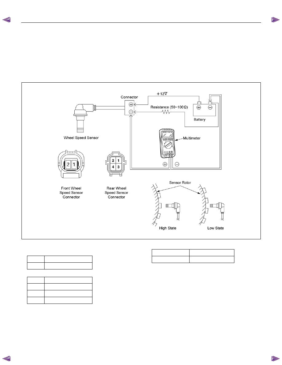
Wheel Speed Sensor Inspection Procedure
Procedure
1.Ignition "OFF".
2.Disconnect each of the wheel speed sensors.
3.Connect the resistance (50
Ω~100Ω) as follows.
4.Check the voltage at sensor harness connector.
Note: Voltage measurement is performed in the phase
where the wheel speed sensor is installed in vehicles.
RTW75AMF000701
Connector Pin-outs
・Front Wheel Speed Sensor
1 (+)
(+12V)
2 (-)
(signal)
・Rear Wheel Speed Sensor
1
LH (+) (+12V)
2
LH (-) (signal)
3 RH
(+)(+12V)
4
RH (-) (signal)
Output Value
High State
0.7~1.4V (±30%)
Low State
0.4~0.7V (±30%)

5A-42 BRAKE CONTROL SYSTEM
Symptom Diagnosis
The symptoms that cannot be indicated by warning
lamp can be divided into the following six categories:
1. ABS works frequently but vehicle does not
decelerate.
2. Uneven braking occurs while ABS works.
3. The wheels are locked.
4. Brake pedal feel is abnormal.
5. Braking sound (from EHCU) is heard while not
braking.
6. No ABS warning lamp
These are all attributable to problems which cannot be
detected by EHCU self-diagnosis. Use the customer
complaint and a test to determine which symptom is
present.
ABS Works Frequently But Vehicle Does Not Decelerate
Step Action Value(s) Yes
No
1
Is braking force distribution normal between front and
rear of vehicle?
-
Go to Step 2
Repair brake
parts.
Go to Step 7
2
Are axle parts installed normally?
-
Go to Step 3
Repair axle
parts.
Go to Step 7
3
Is there play in each or any wheel speed sensor?
-
Repair wheel
speed sensor.
Go to Step 7
Go to Step 4
4
Is there damage, or powered iron sticking to each or
any wheel speed sensor/sensor rotor?
-
Replace
wheel speed
sensor or
sensor rotor.
Go to Step 7
Go to Step 5
5
Is the speed sensor of each wheel output normal?
-
Go to Step 6
Replace
wheel speed
sensor or
repair
harness.
Go to Step 7
6
Is the 4WD control system function normal?
-
2-4WD Repair
or Go to Step
7
Repair or
replace 2-
4WD control
System.
Go to Step 7
7
Reconnect all components, ensure all components
are properly mounted.
Is this step finished?
-
Repeat the
“Basic
diagnostic
flow chart”
Go to Step 7
Нет комментариевНе стесняйтесь поделиться с нами вашим ценным мнением.
Текст