Isuzu KB P190. Manual — part 1446
10-26 CAB
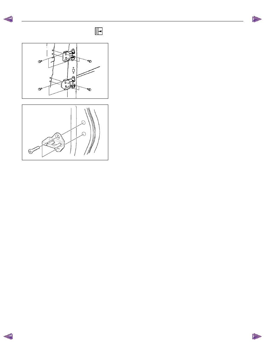
ADJUSTMENT (REAR)
Door Hinge
Door alignment can be obtained by moving door hinges.
Prior to adjustment, set the door temporarily.
Loosen the hinge to door bolts when adjusting steps between
the door and body.
Loosen the hinge to body bolts to adjust the clearance between
the door and body.
Door Striker
Loosen the striker screws and adjust the position of the striker
by holding a piece of wood against the striker and tapping it
with a hammer.
To obtain correct adjustment, move the position of the striker
vertically so that the lower face of the dovetail becomes parallel
to the striker.
CAB 10-27
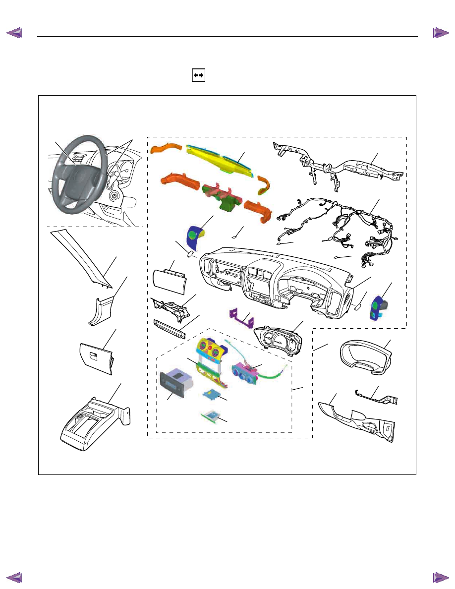
INSTRUMENT PANEL
REMOVAL
9
8
2
1
7
4
3
12
21
20
15
19
22
18
14
16
13
17
24
23
11
25
28
26
24
10
10
27
11
5
6
10
This illustration is based on RHD model
RTW7A0LF001301
Disassembly Steps
▲ 1. Front console assembly
▲ 2. Glove box
▲ 3. Instrument panel driver lower cover
assembly
▲ 4. Driver knee bolster assembly
▲ 5. Driver air bag
▲ 6. Steering wheel/ steering cowl
8. Dash side trim cover
9. Front pillar trim cover
10. Front cover
11. Side cover
▲ 12. Instrument panel assembly & Cross
beam
▲ 13. Ashtray case

10-28 CAB
▲ 7. Meter cluster assembly
▲ 14. Center cluster assembly
15. Audio bracket
▲ 16. Control lever assembly
17. Audio assembly
▲ 18. Ashtray bracket
19. Center cluster
20. Meter assembly
21. Passenger lower bracket
22. Glove box cover
▲ 23. Passenger air bag (if so equipped)
▲ 24. Side ventilation grille
▲ 25. Vent duct assembly/Defroster nozzle
assembly
26. Instrument harness assembly
▲ 27. Instrument panel assembly
28. Cross beam
CAB 10-29
Important Operations
1. Front Console Assembly
• Refer to Floor Consol in this section.
RTW6A0SH000101
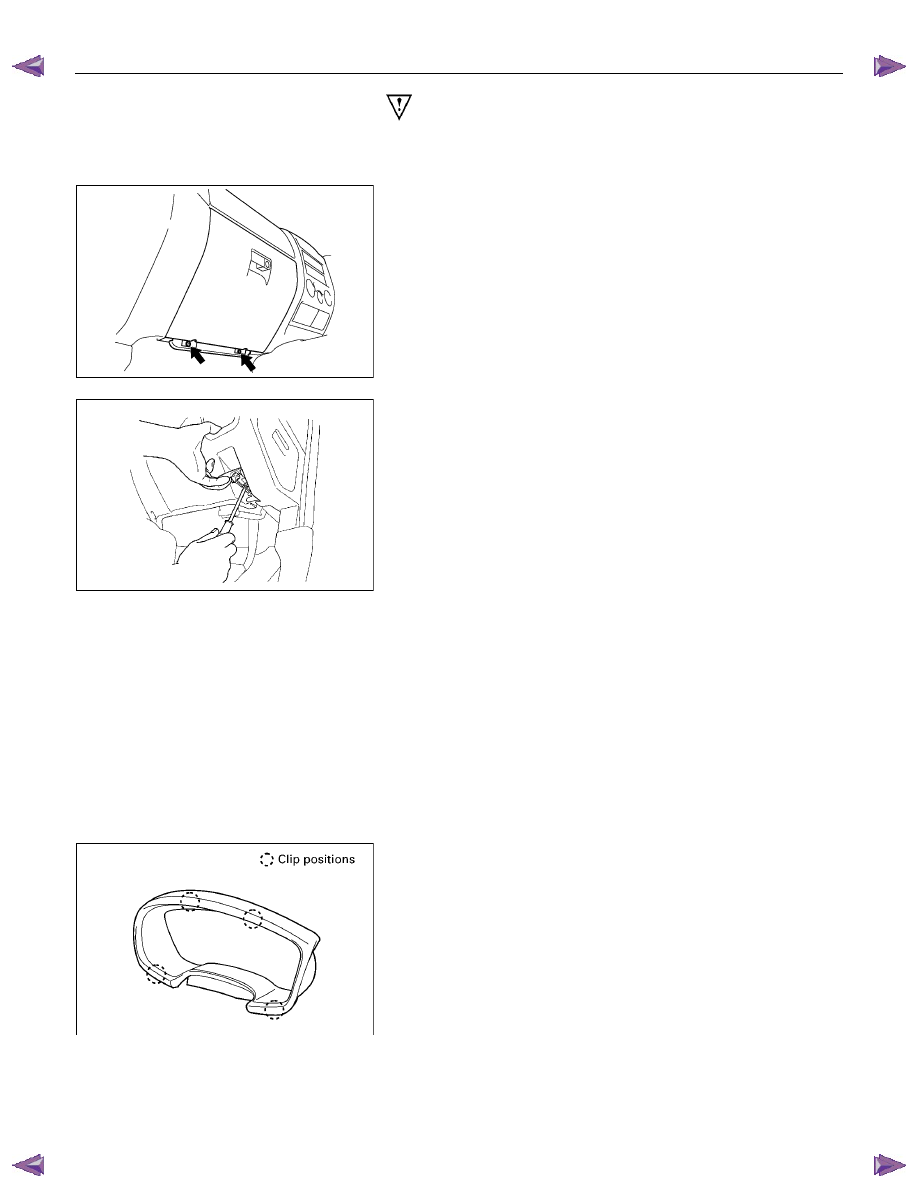
2. Glove Box
• Remove 2 fixing screws and pull on the handle.
RTW6A0SH000201
3. Instrument Panel Driver Lower Cover Assembly
1) Remove the engine hood opener 2 fixing screws.
2) Remove the lower cover one fixing screw.
3) Pull out the cover (Stick type parking brake only).
4) Pull out the lower cover assembly.
4. Driver Knee Bolster Assembly
• Remove 4 fixing bolts.
Caution:
For precautions on installation or removal of the SRS-air
bag system, refer to section 9 “Supplemental Restraint
System (SRS) - AIR BAG”
5. Driver Air Bag
6. Steering Wheel/Steering Cowl
• Refer to Section 3B “STEERING COLUMN” for steering
lock assembly removal steps.
7. Meter Cluster Assembly
• Pull out the 4 clip positions.
Нет комментариевНе стесняйтесь поделиться с нами вашим ценным мнением.
Текст