Isuzu KB P190. Manual — part 314

6E-222 Engine Control System (4JH1)
DTC P1625 (Symptom Code A) (Flash Code 76)
Circuit Description
The engine control module (ECM) main relay is
energized when the ECM receives an ignition voltage
switch ON signal. When the ignition switch is OFF, the
ECM main relay is de-energized after a certain length of
time passed. If the ECM detects the ECM main relay is
turned OFF before ECM commanded OFF, this DTC
will set.
Condition for Setting the DTC
• The ECM detects that the ECM main relay is
turned OFF before commanded turned OFF.
Action Taken When the DTC Sets
• The ECM does not illuminate the malfunction
indicator lamp (MIL) when the diagnostic runs and
fails.
Condition for Clearing the DTC
• A history DTC clears after 40 consecutive driving
cycles without a fault. Or clear with the scan tool.
Diagnostic Aids
• If an intermittent condition is suspected, refer to
Intermittent Conditions in this section.
• Faulty ECM main relay may set this DTC.
DTC P1625 (Symptom Code A) (Flash Code 76)
Schematic Reference: Engine Controls Schematics
Connector End View Reference: Engine Controls
Connector End Views or Engine Control Module (ECM)
Connector End Views
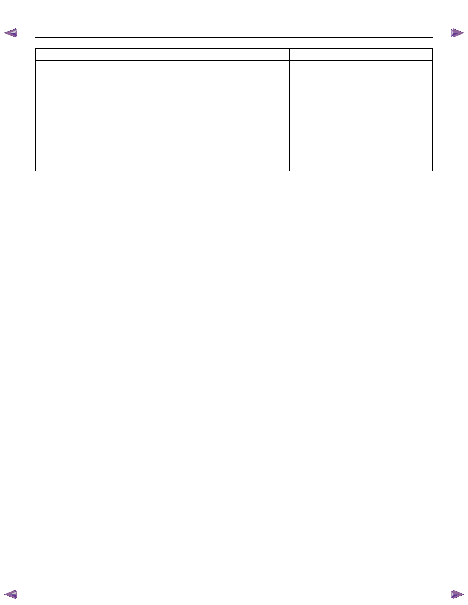
Step Action
Value(s)
Yes
No
1
Did you perform the Diagnostic System Check-
Engine Controls?
Go to Step 2
Go to Diagnostic
System Check-
Engine Controls
2
1. Install the scan tool.
2. Turn OFF the ignition for 30 seconds.
3. Turn ON the ignition, with the engine OFF.
4. Monitor the Diagnostic Trouble Code (DTC)
Information with the scan tool.
5. Turn OFF the ignition.
6. Turn ON the ignition, with the engine OFF.
Does the DTC fail this ignition?
Go to Step 3
Go to Diagnostic
Aids
3
1. Turn OFF the ignition.
2. Disconnect the ECM main relay.
3. Inspect for an intermittent, for poor connections
and corrosion at the harness connector of the
ECM main relay (pins 1, 2, 4 and 5 of X-12
connector).
4. Disconnect the engine control module (ECM)
harness connector.
5. Inspect for an intermittent, for poor connections
and corrosion on ECM main relay control and
battery voltage feed circuit at the harness
connector of the ECM (pins 3 and 58 of C-56
connector).
6. Test for high resistance on each ECM main relay
circuit.
7. Repair the connection(s) or circuit(s) as
necessary.
Did you find and correct the condition?
Go to Step 5
Go to Step 4
4
Replace the ECM main relay.
Did you complete the replacement?
Go to Step 5
Engine Control System (4JH1) 6E-223
Step Action
Value(s)
Yes
No
5
1. Reconnect all previously disconnected relay or
harness connector(s).
2. Clear the DTCs with the scan tool.
3. Turn OFF the ignition for 30 seconds.
4. Start the engine.
5. Observe the DTC Information with the scan tool.
6. Turn OFF the ignition.
7. Turn ON the ignition, with the engine OFF.
Does the DTC fail this ignition?
Go to Step 3
Go to Step 6
6
Observe the DTC Information with the scan tool.
Are there any DTCs that you have not diagnosed?
Go to Diagnostic
Trouble Code (DTC)
List System
OK

6E-224 Engine Control System (4JH1)
DTC P1625 (Symptom Code B) (Flash Code 76)
Circuit Description
The engine control module (ECM) main relay is
energized when the ECM receives an ignition voltage
switch ON signal. When the ignition switch is OFF, the
ECM main relay is de-energized after a certain length of
time passed. If the ECM detects the ECM main relay
has been ON since the ignition switch was turned OFF,
this DTC will set.
Condition for Running the DTC
• The ignition switch is OFF.
Condition for Setting the DTC
• The ECM detects that the ECM main relay is
turned ON for longer than 2 seconds.
Action Taken When the DTC Sets
• The ECM does not illuminate the malfunction
indicator lamp (MIL) when the diagnostic runs and
fails.
Condition for Clearing the DTC
• A history DTC clears after 40 consecutive driving
cycles without a fault. Or clear with the scan tool.
Diagnostic Aids
• If an intermittent condition is suspected, refer to
Intermittent Conditions in this section.
• Faulty or sticking ECM main relay may set this
DTC.
Test Description
The numbers below refer to the step number on the
diagnostic table.
2. If this DTC is present, scan tool can communicate
with the ECM when the ignition switch is OFF.
DTC P1625 (Symptom Code B) (Flash Code 76)
Schematic Reference: Engine Controls Schematics
Connector End View Reference: Engine Controls
Connector End Views or Engine Control Module (ECM)
Connector End Views
Step Action
Value(s)
Yes
No
1
Did you perform the Diagnostic System Check-
Engine Controls?
Go to Step 2
Go to Diagnostic
System Check-
Engine Controls
2
1. Install the scan tool.
2. Turn OFF the ignition for 30 seconds.
3. Monitor the Diagnostic Trouble Code (DTC)
Information with the scan tool.
Does the DTC fail with the ignition switch OFF?
Go to Step 3
Go to Diagnostic
Aids
3
1. Disconnect the ECM main relay.
2. Monitor the DTC Information with the scan tool.
Does the DTC fail with the ignition switch OFF?
Go to Step 6
Go to Step 4
4
1. Turn OFF the ignition.
2. Disconnect the ECM main relay.
3. Connect a test lamp between the control circuit
of the ECM main relay harness (pin 4 of X-12
connector) and battery voltage.
4. Keep the ignition switch OFF.
Does the test lamp illuminate?
Go to Step 5
Go to Step 7
5
1. Test the control circuit of the ECM main relay
between the engine control module (ECM) (pin
58 of C-56 connector) and the ECM main relay
(pin 4 of X-12 connector) for a short to ground.
2. Repair the circuit(s) as necessary.
Did you find and correct the condition?
Go to Step 9
Go to Step 8
6
Repair the short to battery on the voltage feed
supply circuit to the ECM between the ECM (pin 3 of
C-56 connector) and the ECM main relay (pin 1 of X-
12 connector).
Did you complete the repair?
Go to Step 9
7
Replace the ECM main relay.
Did you complete the replacement?
Go to Step 9
Engine Control System (4JH1) 6E-225
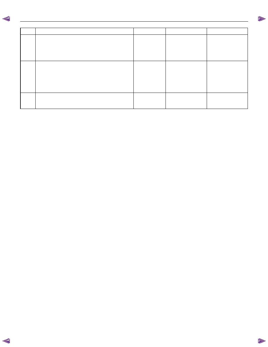
Step Action
Value(s)
Yes
No
8
Important: Replacement ECM must be
programmed.
Replace the ECM. Refer to Engine Control Module
(ECM) Replacement in this section.
Did you complete the replacement?
Go to Step 9
9
1. Reconnect all previously disconnected relay or
harness connector(s).
2. Clear the DTCs with the scan tool.
3. Turn OFF the ignition for 30 seconds.
4. Monitor the DTC Information with the scan tool.
Does the DTC with the ignition switch OFF?
Go to Step 3
Go to Step 10
10
Observe the DTC Information with the scan tool.
Are there any DTCs that you have not diagnosed?
Go to Diagnostic
Trouble Code (DTC)
List System
OK
Нет комментариевНе стесняйтесь поделиться с нами вашим ценным мнением.
Текст