Qashqai J11. Horn. Service and Repair Manual
Qashqai J11. Horn. Service and Repair Manual
HRN-1
DRIVER CONTROLS
C
D
E
F
G
H
I
J
K
M
SECTION
HRN
A
B
HRN
N
O
P
CONTENTS
HORN
PRECAUTION . . . . . . . . . . . ...
PRECAUTIONS . . . . . . . . . . . . ...
Precautions for Removing Battery Terminal . . .....
WIRING DIAGRAM . . . . . . . . . ...
HORN . . . . . . . . . . . . . . . . .
Wiring Diagram . . . . . . . . . . . . . . .
REMOVAL AND INSTALLATION . . . .
HORN . . . . . . . . . . . . . . . . .
Exploded View . . . . . . . . . . . . . . ..
HRN-2
< PRECAUTION >
PRECAUTIONS
PRECAUTION
PRECAUTIONS
Precaution for Supplemental Restraint System (SRS) "AIR BAG" and "SEAT BELT
PRE-TENSIONER"
INFOID:0000000010339331
The Supplemental Restraint System such as “AIR BAG” and “SEAT BELT PRE-TENSIONER”, used along
with a front seat belt, helps to reduce the risk or severity of injury to the driver and front passenger for certain
types of collision. Information necessary to service the system safely is included in the “SRS AIR BAG” and
“SEAT BELT” of this Service Manual.
WARNING:
Always observe the following items for preventing accidental activation.
• To avoid rendering the SRS inoperative, which could increase the risk of personal injury or death in
the event of a collision that would result in air bag inflation, all maintenance must be performed by
an authorized NISSAN/INFINITI dealer.
• Improper maintenance, including incorrect removal and installation of the SRS, can lead to personal
injury caused by unintentional activation of the system. For removal of Spiral Cable and Air Bag
Module, see “SRS AIR BAG”.
• Never use electrical test equipment on any circuit related to the SRS unless instructed to in this Ser-
vice Manual. SRS wiring harnesses can be identified by yellow and/or orange harnesses or harness
connectors.
PRECAUTIONS WHEN USING POWER TOOLS (AIR OR ELECTRIC) AND HAMMERS
WARNING:
Always observe the following items for preventing accidental activation.
• When working near the Air Bag Diagnosis Sensor Unit or other Air Bag System sensors with the
ignition ON or engine running, never use air or electric power tools or strike near the sensor(s) with
a hammer. Heavy vibration could activate the sensor(s) and deploy the air bag(s), possibly causing
serious injury.
• When using air or electric power tools or hammers, always switch the ignition OFF, disconnect the
battery, and wait at least 3 minutes before performing any service.
Precautions for Removing Battery Terminal
INFOID:0000000010503743
• With the adoption of Auto ACC function, ACC power is automatically supplied by operating the intelligent key
or remote keyless entry or by opening/closing the driver side door. In addition, ACC power is supplied even
after the ignition switch is turned to the OFF position, i.e. ACC power is supplied for a certain fixed time.
• When disconnecting the 12V battery terminal, turn off the ACC
power before disconnecting the 12V battery terminal, observing
“How to disconnect 12V battery terminal” described below.
NOTE:
Some ECUs operate for a certain fixed time even after ignition
switch is turned OFF and ignition power supply is stopped. If the
battery terminal is disconnected before ECU stops, accidental DTC
detection or ECU data damage may occur.
• For vehicles with the 2-batteries, be sure to connect the main bat-
tery and the sub battery before turning ON the ignition switch.
NOTE:
If the ignition switch is turned ON with any one of the terminals of
main battery and sub battery disconnected, then DTC may be detected.
• After installing the 12V battery, always check "Self Diagnosis Result" of all ECUs and erase DTC.
NOTE:
The removal of 12V battery may cause a DTC detection error.
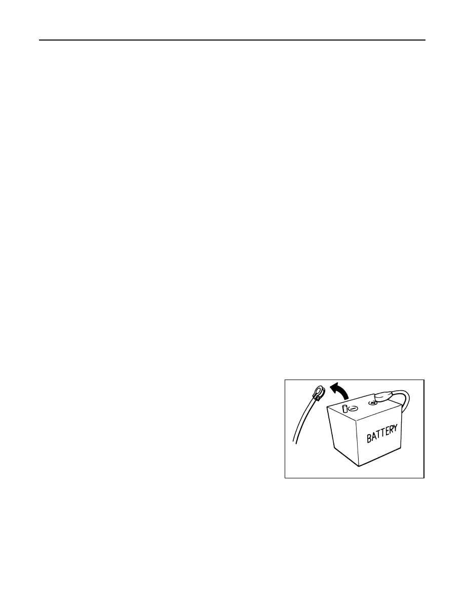
HOW TO DISCONNECT 12V BATTERY TERMINAL
Disconnect 12V battery terminal according to instruction described below.
1.
Open the hood.
2.
Turn ignition switch to the ON position.
3.
Turn ignition switch to the OFF position with the driver side door opened.
4.
Get out of the vehicle and close the driver side door.
SEF289H
PRECAUTIONS
HRN-3
< PRECAUTION >
C
D
E
F
G
H
I
J
K
M
A
B
HRN
N
O
P
5.
Wait at least 3 minutes. For vehicle with the engine listed below, remove the battery terminal after a lapse
of the specified time.
CAUTION:
While waiting, never operate the vehicle such as locking, opening, and closing doors. Violation of
this caution results in the activation of ACC power supply according to the Auto ACC function.
6.
Remove 12V battery terminal.
CAUTION:
After installing 12V battery, always check self-diagnosis results of all ECUs and erase DTC.
D4D engine
: 20 minutes
HRA2DDT
: 12 minutes
K9K engine
: 4 minutes
M9R engine
: 4 minutes
R9M engine
: 4 minutes
V9X engine
: 4 minutes
HRN-4
< WIRING DIAGRAM >
HORN
WIRING DIAGRAM
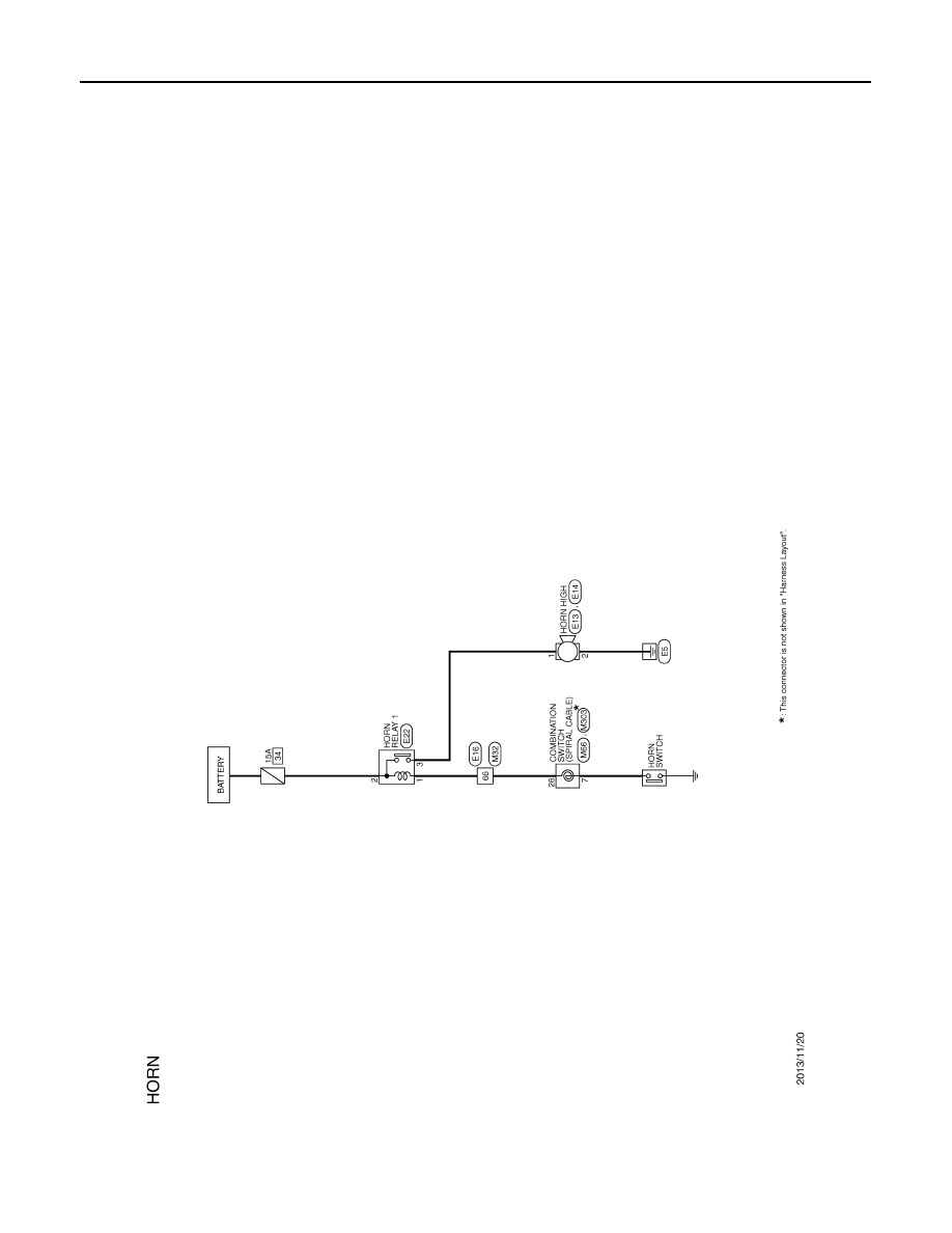
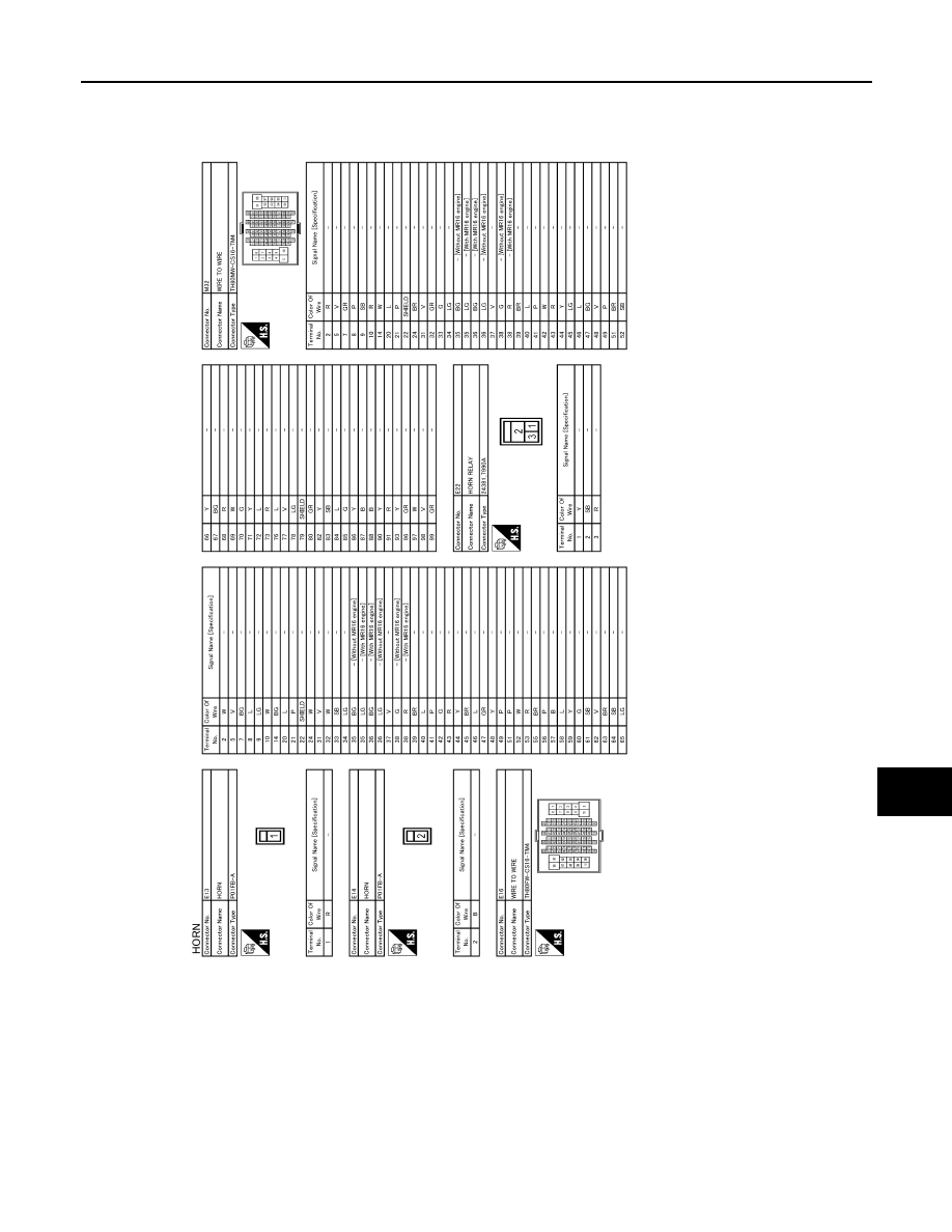
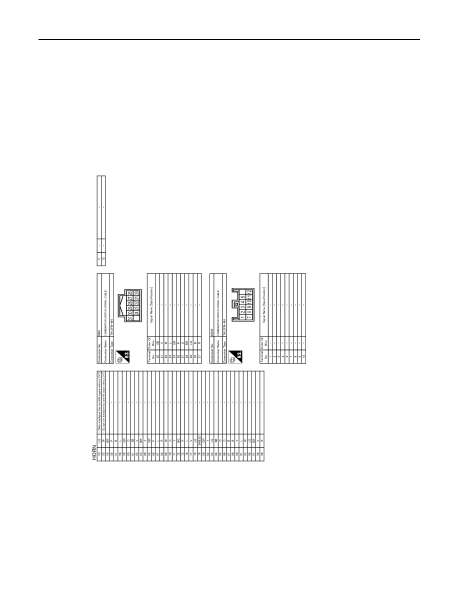
HORN
Wiring Diagram
INFOID:0000000010339333
JRLWD2046GB
HORN
HRN-5
< WIRING DIAGRAM >
C
D
E
F
G
H
I
J
K
M
A
B
HRN
N
O
P
JRLWE4201GB
HRN-6
< WIRING DIAGRAM >
HORN
JRLWE4202GB
HORN
HRN-7
< REMOVAL AND INSTALLATION >
C
D
E
F
G
H
I
J
K
M
A
B
HRN
N
O
P
REMOVAL AND INSTALLATION
HORN
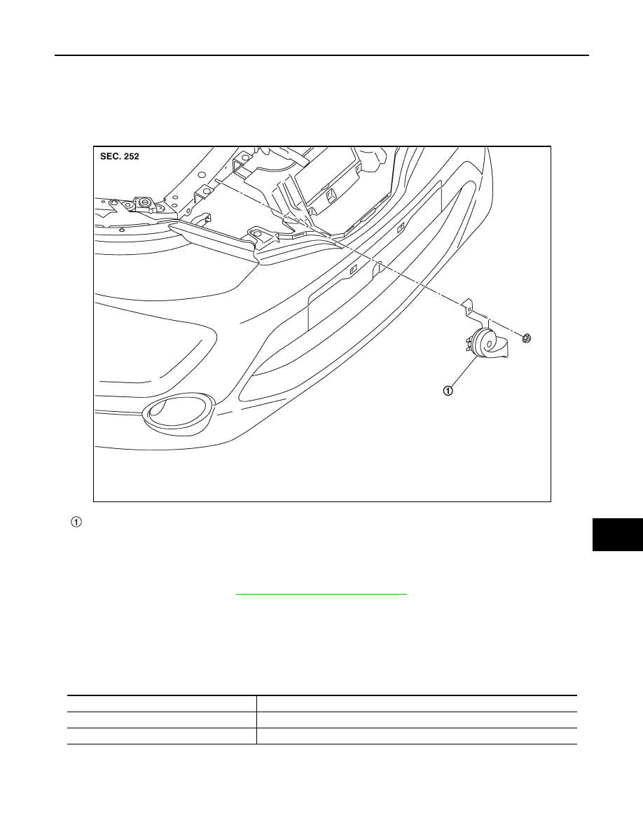
Exploded View
INFOID:0000000010339334
Removal and Installation
INFOID:0000000010339335
REMOVAL
1.
Remove the front grille. Refer to
EXT-25, "Removal and Installation"
2.
Disconnect the horn connectors.
3.
Remove the horn mounting bolt, and remove the horn.
INSTALLATION
Note the following items, and then install in the reverse order of removal.
CAUTION:
Be careful to connect power supply harness connector and ground harness connector normally.
Horn
JMLIA5105ZZ
Harness connector
Horn
Brown
Power supply (terminal with brown plastic base)
Black
Ground (terminal located on horn bracket)
Нет комментариевНе стесняйтесь поделиться с нами вашим ценным мнением.
Текст