Qashqai J11. Power outlet. Service and Repair Manual
PWO
PWO-1
ELECTRICAL & POWER CONTROL
C
D
E
F
G
H
I
J
K
L
B
SECTION
PWO
A
O
P
N
CONTENTS
POWER OUTLET
PRECAUTION . . . . . . . . . . . ...
PRECAUTIONS . . . . . . . . . . . . ...
Precaution Necessary for Steering Wheel Rota-
tion After Battery Disconnect . . . . . . . . .....
Precautions for Removing Battery Terminal . . .....
SYSTEM DESCRIPTION . . . . . . . ..
COMPONENT PARTS . . . . . . . . . ...
Component Parts Location . . . . . . . . . ...
Power Socket . . . . . . . . . . . . . . ...
WIRING DIAGRAM . . . . . . . . . ...
POWER SOCKET . . . . . . . . . . . ..
Wiring Diagram . . . . . . . . . . . . . . .
REMOVAL AND INSTALLATION . . . .
POWER SOCKET . . . . . . . . . . . ..
PWO-2
< PRECAUTION >
PRECAUTIONS
PRECAUTION
PRECAUTIONS
Precaution for Supplemental Restraint System (SRS) "AIR BAG" and "SEAT BELT
PRE-TENSIONER"
INFOID:0000000010437037
The Supplemental Restraint System such as “AIR BAG” and “SEAT BELT PRE-TENSIONER”, used along
with a front seat belt, helps to reduce the risk or severity of injury to the driver and front passenger for certain
types of collision. Information necessary to service the system safely is included in the “SRS AIR BAG” and
“SEAT BELT” of this Service Manual.
WARNING:
Always observe the following items for preventing accidental activation.
• To avoid rendering the SRS inoperative, which could increase the risk of personal injury or death in
the event of a collision that would result in air bag inflation, all maintenance must be performed by
an authorized NISSAN/INFINITI dealer.
• Improper maintenance, including incorrect removal and installation of the SRS, can lead to personal
injury caused by unintentional activation of the system. For removal of Spiral Cable and Air Bag
Module, see “SRS AIR BAG”.
• Never use electrical test equipment on any circuit related to the SRS unless instructed to in this Ser-
vice Manual. SRS wiring harnesses can be identified by yellow and/or orange harnesses or harness
connectors.
PRECAUTIONS WHEN USING POWER TOOLS (AIR OR ELECTRIC) AND HAMMERS
WARNING:
Always observe the following items for preventing accidental activation.
• When working near the Air Bag Diagnosis Sensor Unit or other Air Bag System sensors with the
ignition ON or engine running, never use air or electric power tools or strike near the sensor(s) with
a hammer. Heavy vibration could activate the sensor(s) and deploy the air bag(s), possibly causing
serious injury.
• When using air or electric power tools or hammers, always switch the ignition OFF, disconnect the
battery, and wait at least 3 minutes before performing any service.
Precaution Necessary for Steering Wheel Rotation After Battery Disconnect
INFOID:0000000010504891
CAUTION:
Comply with the following cautions to prevent any error and malfunction.
• Before removing and installing any control units, first turn the ignition power source and accessory
power source to the OFF, then disconnect both battery cables.
• After finishing work, confirm that all control unit connectors are connected properly, then re-connect
both battery cables.
• Always use CONSULT to perform self-diagnosis as a part of each function inspection after finishing
work. If a DTC is detected, perform trouble diagnosis according to self-diagnosis results.
For vehicle with steering lock unit, if the battery is disconnected or discharged, the steering wheel will lock and
cannot be turned.
If turning the steering wheel is required with the battery disconnected or discharged, follow the operation pro-
cedure below before starting the repair operation.
OPERATION PROCEDURE
1.
Connect both battery cables.
NOTE:
Supply power using jumper cables if battery is discharged.
2.
Open driver door.
3.
Turn the ignition switch to the ON position.
(At this time, the steering lock will be released.)
4.
Turn the ignition switch to OFF position with driver door open.
5.
Wait for 3 minutes or longer with driver door open.
NOTE:
• Do not close driver door because the steering wheel locks when driver door is closed.
PWO
PRECAUTIONS
PWO-3
< PRECAUTION >
C
D
E
F
G
H
I
J
K
L
B
A
O
P
N
• The auto acc function is adapted to this vehicle. For this reason, even when the ignition switch is turned
to OFF position, the accessory power source does not turned OFF and continues to be supplied for a
certain amount of time.
6.
Disconnect both battery cables. The steering lock will remain released with both battery cables discon-
nected and the steering wheel can be turned.
7.
Perform the necessary repair operation.
8.
When the repair work is completed, re-connect both battery cables. With the brake pedal released, turn
the ignition switch from OFF position to ON position, then to LOCK position. (The steering wheel will lock
when the ignition switch is turned to LOCK position.)
9.
Perform self-diagnosis check of all control units using CONSULT.
Precautions for Removing Battery Terminal
INFOID:0000000010504895
• With the adoption of Auto ACC function, ACC power is automatically supplied by operating the intelligent key
or remote keyless entry or by opening/closing the driver side door. In addition, ACC power is supplied even
after the ignition switch is turned to the OFF position, i.e. ACC power is supplied for a certain fixed time.
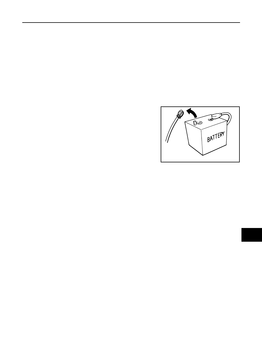
• When disconnecting the 12V battery terminal, turn off the ACC
power before disconnecting the 12V battery terminal, observing
“How to disconnect 12V battery terminal” described below.
NOTE:
Some ECUs operate for a certain fixed time even after ignition
switch is turned OFF and ignition power supply is stopped. If the
battery terminal is disconnected before ECU stops, accidental DTC
detection or ECU data damage may occur.
• For vehicles with the 2-batteries, be sure to connect the main bat-
tery and the sub battery before turning ON the ignition switch.
NOTE:
If the ignition switch is turned ON with any one of the terminals of
main battery and sub battery disconnected, then DTC may be detected.
• After installing the 12V battery, always check "Self Diagnosis Result" of all ECUs and erase DTC.
NOTE:
The removal of 12V battery may cause a DTC detection error.
HOW TO DISCONNECT 12V BATTERY TERMINAL
Disconnect 12V battery terminal according to instruction described below.
1.
Open the hood.
2.
Turn ignition switch to the ON position.
3.
Turn ignition switch to the OFF position with the driver side door opened.
4.
Get out of the vehicle and close the driver side door.
5.
Wait at least 3 minutes. For vehicle with the engine listed below, remove the battery terminal after a lapse
of the specified time.
CAUTION:
While waiting, never operate the vehicle such as locking, opening, and closing doors. Violation of
this caution results in the activation of ACC power supply according to the Auto ACC function.
6.
Remove 12V battery terminal.
CAUTION:
After installing 12V battery, always check self-diagnosis results of all ECUs and erase DTC.
SEF289H
D4D engine
: 20 minutes
HRA2DDT
: 12 minutes
K9K engine
: 4 minutes
M9R engine
: 4 minutes
R9M engine
: 4 minutes
V9X engine
: 4 minutes
PWO-4
< SYSTEM DESCRIPTION >
COMPONENT PARTS
SYSTEM DESCRIPTION
COMPONENT PARTS
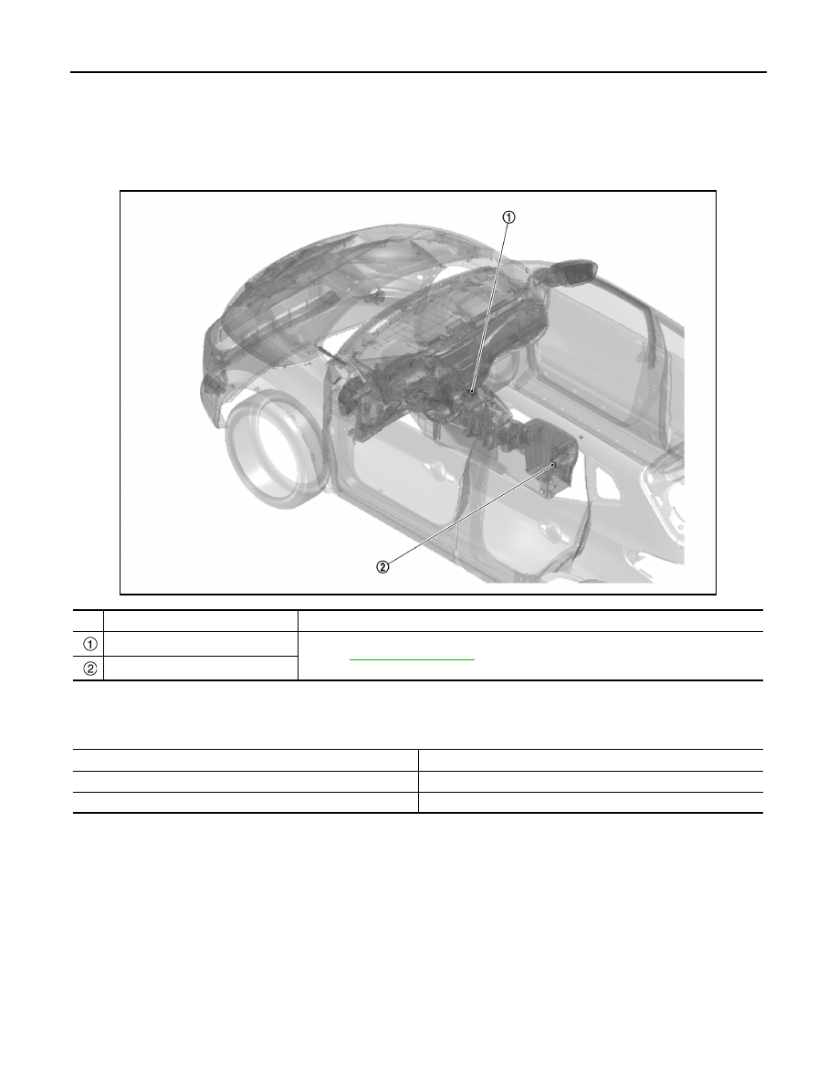
Component Parts Location
INFOID:0000000010437040
Power Socket
INFOID:0000000010437041
No.
Component
Function
Power socket 1
Power socket 2
JMMIA1767ZZ
Rated voltage
DC 12 V
Maximum electric capacity
120 W or less (Total)
Maximum current
10 A or less (Total)
PWO
POWER SOCKET
PWO-5
< WIRING DIAGRAM >
C
D
E
F
G
H
I
J
K
L
B
A
O
P
N
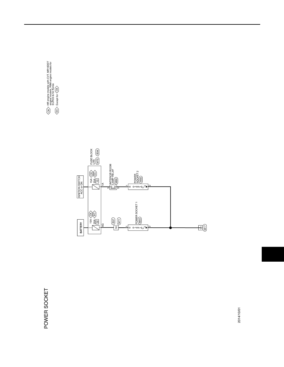
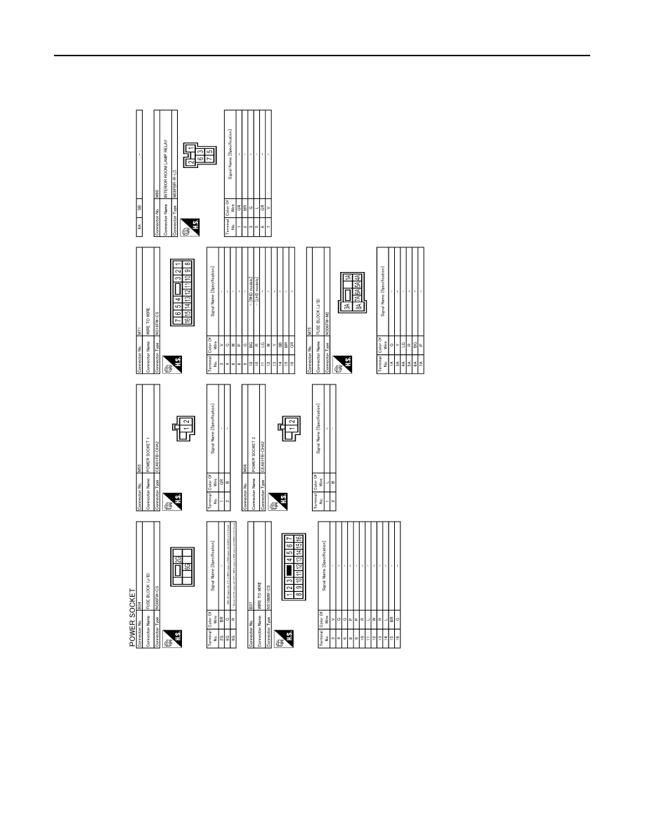
WIRING DIAGRAM
POWER SOCKET
Wiring Diagram
INFOID:0000000010437042
JRMWG7330GB
PWO-6
< WIRING DIAGRAM >
POWER SOCKET
JRMWG7331GB
PWO
POWER SOCKET
PWO-7
< REMOVAL AND INSTALLATION >
C
D
E
F
G
H
I
J
K
L
B
A
O
P
N
REMOVAL AND INSTALLATION
POWER SOCKET
Removal and Installation
INFOID:0000000010437043
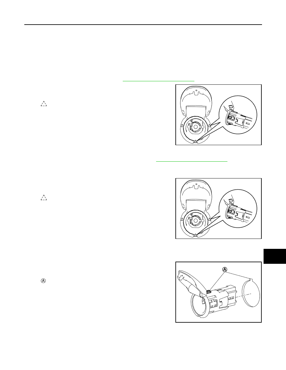
REMOVAL
Instrument Panel Side
1.
Remove upper console finisher. Refer to
IP-19, "Removal and Installation"
2.
Press power socket pawl from back of upper console finisher to
remove power socket.
Center Console Side
1.
Remove center console rear finisher assembly. Refer to
IP-19, "Removal and Installation"
2.
Disconnect power socket harness connector.
3.
Fully open console lid.
4.
Press power socket pawl from back of console box to remove
power socket.
INSTALLATION
Note the following item, and then install in the reverse order of removal.
CAUTION:
Align the cut outs of power socket and center console assem-
bly.
: Pawl
JSMIA1116ZZ
: Pawl
JSMIA1116ZZ
: Cut out
JSMIA1119ZZ
Нет комментариевНе стесняйтесь поделиться с нами вашим ценным мнением.
Текст