Qashqai J11. Accelerator Control System. Service and Repair Manual
Qashqai J11. Accelerator Control System. Service and Repair Manual
ACC-1
ENGINE
C
D
E
F
G
H
I
J
K
L
M
SECTION
ACC
A
ACC
N
O
P
CONTENTS
ACCELERATOR CONTROL SYSTEM
PRECAUTION . . . . . . . . . . . ...
PRECAUTIONS . . . . . . . . . . . . ...
REMOVAL AND INSTALLATION . . . .
ACCELERATOR CONTROL SYSTEM . . . ...
Exploded View . . . . . . . . . . . . . . ..
Removal and Installation . . . . . . . . . . ..
Inspection . . . . . . . . . . . . . . . . .
SERVICE DATA AND SPECIFICATIONS
(SDS) . . . . . . . . . . . . . . . .
SERVICE DATA AND SPECIFICATIONS
(SDS) . . . . . . . . . . . . . . . . ..
ACC-2
< PRECAUTION >
PRECAUTIONS
PRECAUTION
PRECAUTIONS
Precaution for Supplemental Restraint System (SRS) "AIR BAG" and "SEAT BELT
PRE-TENSIONER"
INFOID:0000000010305308
The Supplemental Restraint System such as “AIR BAG” and “SEAT BELT PRE-TENSIONER”, used along
with a front seat belt, helps to reduce the risk or severity of injury to the driver and front passenger for certain
types of collision. Information necessary to service the system safely is included in the “SRS AIR BAG” and
“SEAT BELT” of this Service Manual.
WARNING:
Always observe the following items for preventing accidental activation.
• To avoid rendering the SRS inoperative, which could increase the risk of personal injury or death in
the event of a collision that would result in air bag inflation, all maintenance must be performed by
an authorized NISSAN/INFINITI dealer.
• Improper maintenance, including incorrect removal and installation of the SRS, can lead to personal
injury caused by unintentional activation of the system. For removal of Spiral Cable and Air Bag
Module, see “SRS AIR BAG”.
• Never use electrical test equipment on any circuit related to the SRS unless instructed to in this Ser-
vice Manual. SRS wiring harnesses can be identified by yellow and/or orange harnesses or harness
connectors.
PRECAUTIONS WHEN USING POWER TOOLS (AIR OR ELECTRIC) AND HAMMERS
WARNING:
Always observe the following items for preventing accidental activation.
• When working near the Air Bag Diagnosis Sensor Unit or other Air Bag System sensors with the
ignition ON or engine running, never use air or electric power tools or strike near the sensor(s) with
a hammer. Heavy vibration could activate the sensor(s) and deploy the air bag(s), possibly causing
serious injury.
• When using air or electric power tools or hammers, always switch the ignition OFF, disconnect the
battery, and wait at least 3 minutes before performing any service.
ACCELERATOR CONTROL SYSTEM
ACC-3
< REMOVAL AND INSTALLATION >
C
D
E
F
G
H
I
J
K
L
M
A
ACC
N
P
O
REMOVAL AND INSTALLATION
ACCELERATOR CONTROL SYSTEM
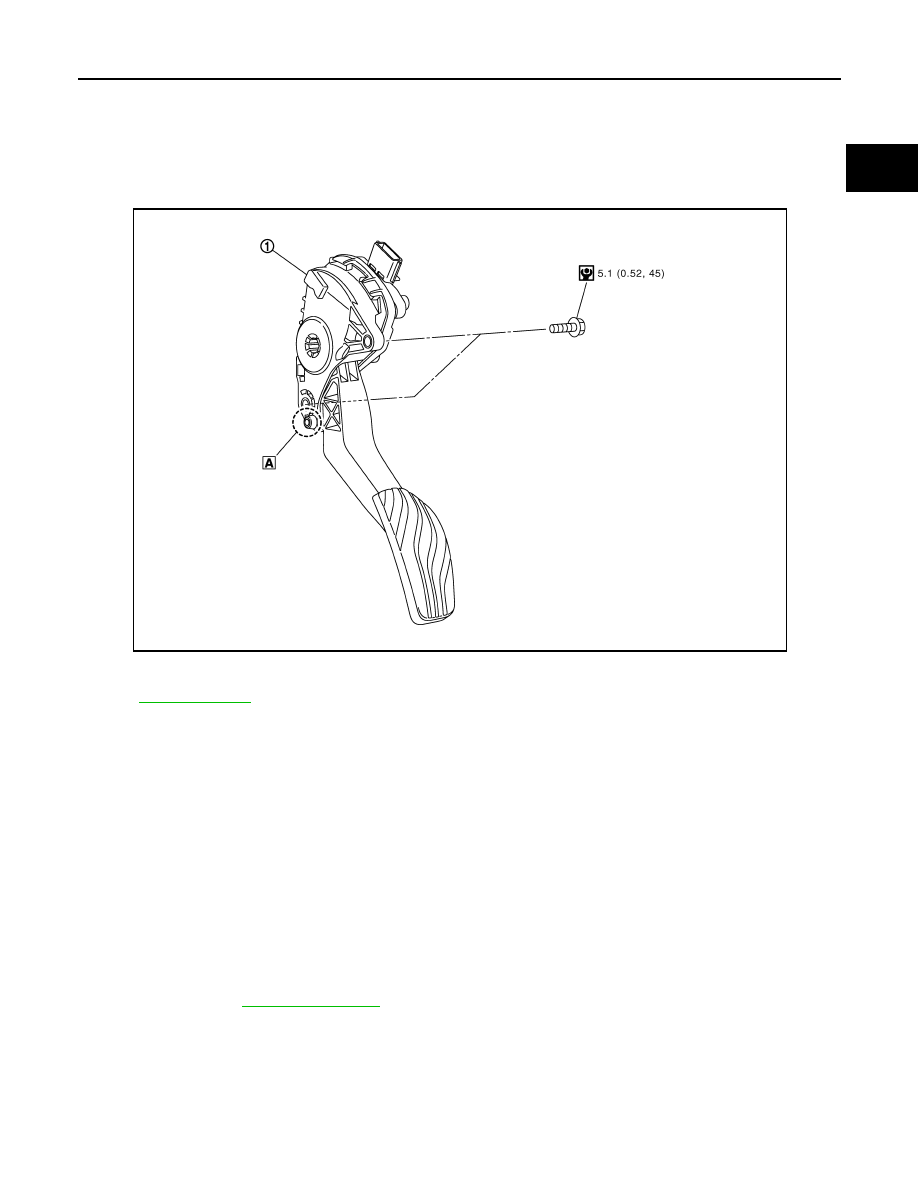
Exploded View
INFOID:0000000010305318
Removal and Installation
INFOID:0000000010305319
REMOVAL
1.
Disconnect the harness connector from the accelerator pedal assembly.
2.
Remove the bolts, then remove accelerator pedal assembly.
CAUTION:
• Never disassemble accelerator lever. Never remove accelerator pedal position sensor from
accelerator lever.
• Avoid impact from dropping etc. during handling.
• Be careful to keep accelerator lever away from water.
INSTALLATION
Note the following, and install in the reverse order of removal.
• Insert locating pin into vehicle side to position accelerator pedal assembly. Install mounting bolt to accelera-
tor pedal assembly.
For inspection, refer to
Inspection
INFOID:0000000010305320
INSPECTION AFTER INSTALLATION
1.
Accelerator pedal assembly
A.
Locating pin
Refer to
for symbols in the figure.
E1BIA1033GB
ACC-4
< REMOVAL AND INSTALLATION >
ACCELERATOR CONTROL SYSTEM
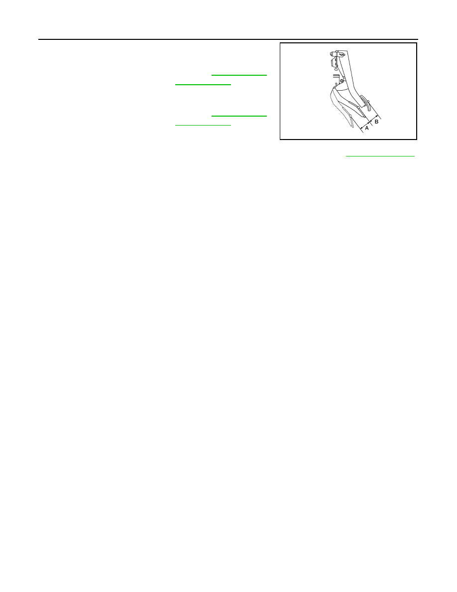
• Check that the accelerator pedal moves smoothly within the speci-
fied range.
• Check the accelerator pedal height.
• If accelerator pedal does not meet specified values, check brake pedal height. Refer to
.
• Depress and release the accelerator pedal to check that it returns quickly and smoothly to the original
released position.
CAUTION:
• Whenever the harness connector of the accelerator pedal position sensor has been disconnected,
perform "Accelerator Pedal Released Position Learning".
• The accelerator pedal should operate smoothly without catching when the pedal operating force is
released. The pedal should return smoothly to the fully raised position. The spring should be free
from damage.
Accelerator pedal stroke (A)
: Refer to
Accelerator pedal stroke (B)
: Refer to
AWBIA1744ZZ
SERVICE DATA AND SPECIFICATIONS (SDS)
ACC-5
< SERVICE DATA AND SPECIFICATIONS (SDS)
C
D
E
F
G
H
I
J
K
L
M
A
ACC
N
P
O
SERVICE DATA AND SPECIFICATIONS (SDS)
SERVICE DATA AND SPECIFICATIONS (SDS)
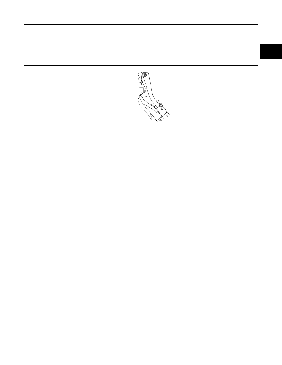
Accelerator Control
INFOID:0000000010427873
Unit: mm (in)
Accelerator pedal stroke (A)
49.6 - 52.4 (1.95 - 2.06)
Pedal height difference between accelerator and brake (B)
35 - 45 (1.38 - 1.77)
AWBIA1744ZZ
Нет комментариевНе стесняйтесь поделиться с нами вашим ценным мнением.
Текст