Nissan GT-R (2007-2014 year). CHARGING SYSTEM / CRUISE CONTROL SYSTEM. Service Manual
CHG
CHG-1
ELECTRICAL & POWER CONTROL
C
D
E
F
G
H
I
J
K
L
B
SECTION
CHG
A
O
P
N
CONTENTS
CHARGING SYSTEM
SYSTEM DESCRIPTION . . . . . . . ..
CHARGING SYSTEM . . . . . . . . . . ..
System Diagram . . . . . . . . . . . . . ....
System Description . . . . . . . . . . . . ...
Component Parts Location . . . . . . . . . ....
Component Description . . . . . . . . . . ....
POWER GENERATION VOLTAGE VARI-
ABLE CONTROL SYSTEM . . . . . . . . .
System Diagram . . . . . . . . . . . . . ....
System Description . . . . . . . . . . . . ...
Component Parts Location . . . . . . . . . ....
Component Description . . . . . . . . . . .....
DTC/CIRCUIT DIAGNOSIS . . . . . . ..
B TERMINAL CIRCUIT . . . . . . . . . ...
Description . . . . . . . . . . . . . . . ....
Diagnosis Procedure . . . . . . . . . . . .....
L TERMINAL CIRCUIT (OPEN) . . . . . . ..
Description . . . . . . . . . . . . . . . ....
Diagnosis Procedure . . . . . . . . . . . .....
CHARGING SYSTEM . . . . . . . . . . ..
Wiring Diagram - CHARGING SYSTEM - . . . .....
PRECAUTION . . . . . . . . . . . ..
PRECAUTIONS . . . . . . . . . . . . .
Precaution for Working Range at a Regular Deal-
ership . . . . . . . . . . . . . . . . . ...
Precautions Necessary for Steering Wheel Rota-
tion After Battery Disconnection . . . . . . . ..
Precaution for Battery Service . . . . . . . . .
Precaution for Power Generation Voltage Variable
Control System . . . . . . . . . . . . . .
PREPARATION . . . . . . . . . . ...
PREPARATION . . . . . . . . . . . . .
Special Service Tools . . . . . . . . . . . ..
Commercial Service Tools . . . . . . . . . ...
PERIODIC MAINTENANCE . . . . . .
CHARGING SYSTEM PRELIMINARY IN-
SPECTION . . . . . . . . . . . . . .
Inspection Procedure . . . . . . . . . . . ...
SERVICE DATA AND SPECIFICATIONS
(SDS) . . . . . . . . . . . . . . .
SERVICE DATA AND SPECIFICATIONS
(SDS) . . . . . . . . . . . . . . . . .
Alternator . . . . . . . . . . . . . . . . .
Revision: 2012 November
2014 GT-R
CHG-2
< SYSTEM DESCRIPTION >
CHARGING SYSTEM
SYSTEM DESCRIPTION
CHARGING SYSTEM
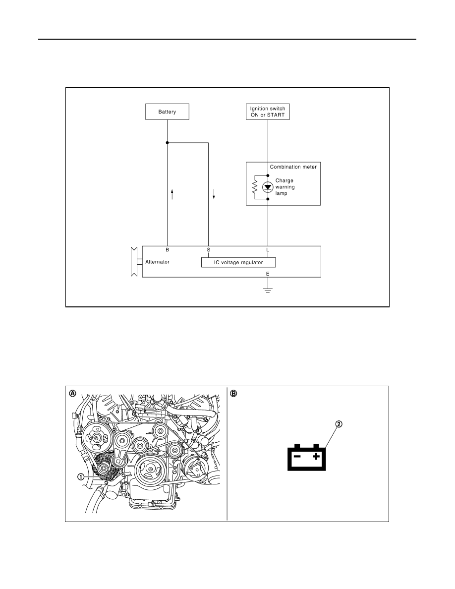
System Diagram
INFOID:0000000009160038
System Description
INFOID:0000000009160039
The alternator provides DC voltage to operate the vehicle's electrical system and to keep the battery charged.
The voltage output is controlled by the IC voltage regulator.
Component Parts Location
INFOID:0000000009160040
JPMIA0426GB
1.
Alternator
2.
Charge warning lamp
A.
Cylinder block (bank 1) side
B.
Combination meter
NNMIA0001ZZ
Revision: 2012 November
2014 GT-R
CHG
CHARGING SYSTEM
CHG-3
< SYSTEM DESCRIPTION >
C
D
E
F
G
H
I
J
K
L
B
A
O
P
N
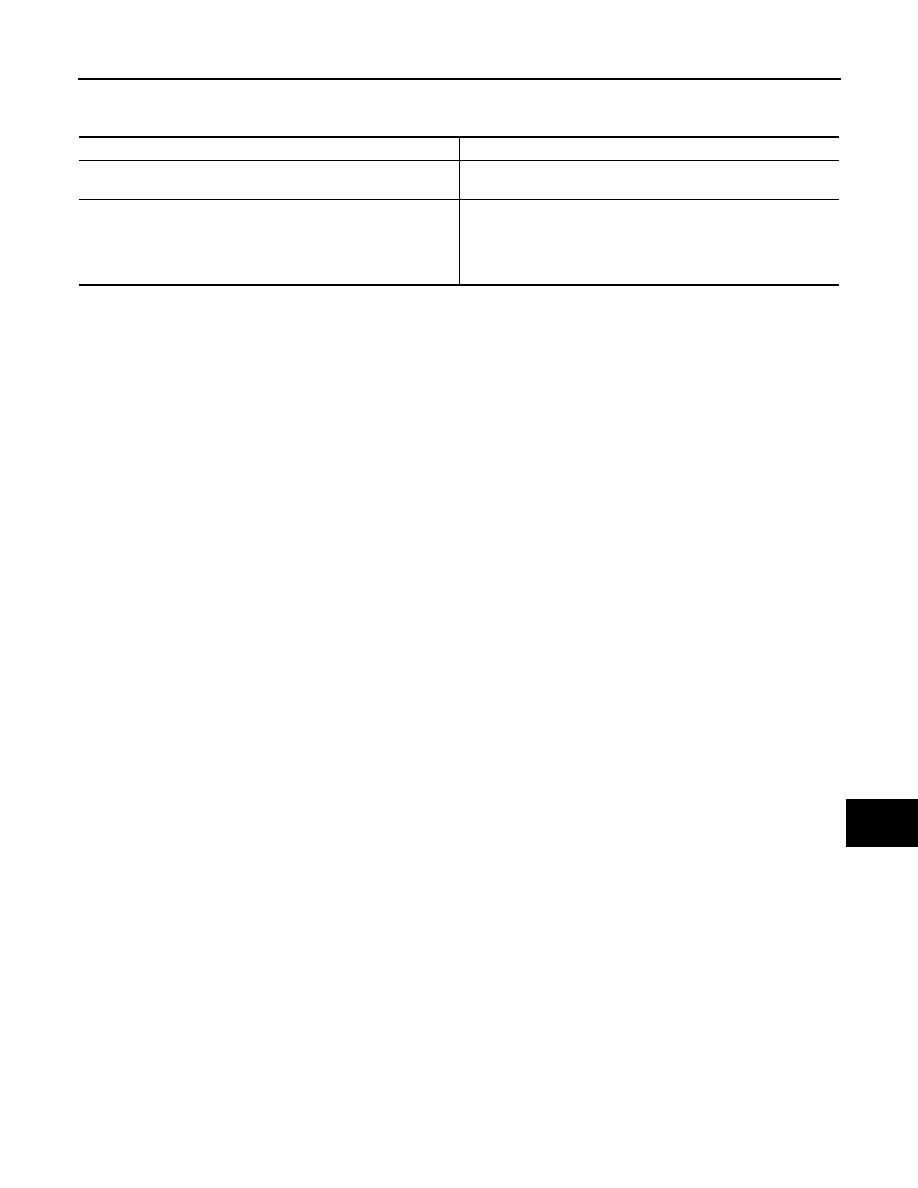
Component Description
INFOID:0000000009160041
Component part
Description
Alternator
The alternator provides DC voltage to operate the vehicle electri-
cal system and to keep the battery charged.
Combination meter (Charge warning lamp)
The IC voltage regulator warning function activates to illuminate
the charge warning lamp, if any of the following symptoms occur
while alternator is operating:
• Excessive voltage is produced.
• No voltage is produced.
Revision: 2012 November
2014 GT-R
CHG-4
< SYSTEM DESCRIPTION >
POWER GENERATION VOLTAGE VARIABLE CONTROL SYSTEM
POWER GENERATION VOLTAGE VARIABLE CONTROL SYSTEM
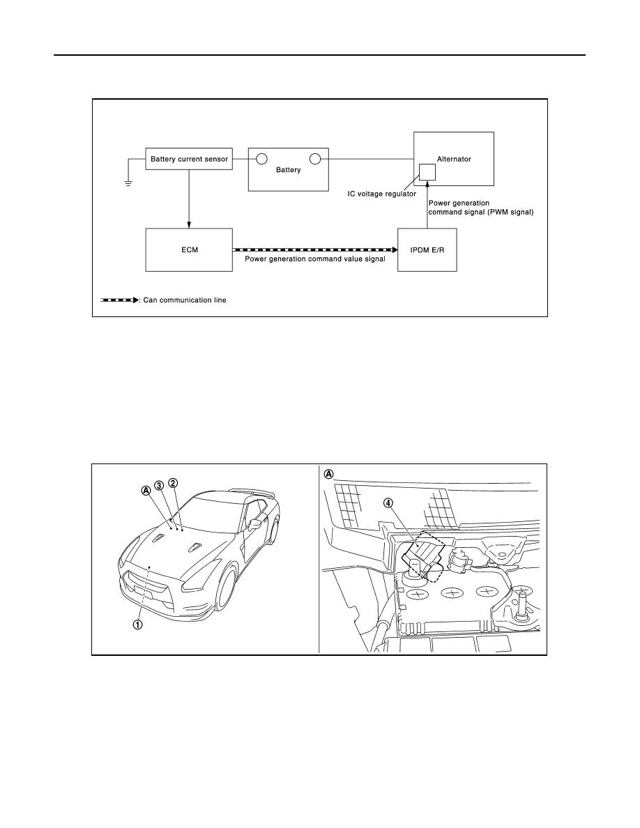
System Diagram
INFOID:0000000009160042
System Description
INFOID:0000000009160043
By performing the power generation voltage variable control, the engine load due to the power generation of
the alternator is reduced and fuel consumption is decreased.
NOTE:
When any malfunction is detected in the power generation voltage variable control system, the power genera-
tion is performed according to the characteristic of the IC voltage regulator of the alternator.
Component Parts Location
INFOID:0000000009160044
JMMIA0388GB
1.
Alternator
2.
ECM
3.
IPDM E/R
4.
Battery current sensor
A.
Battery
NNMIB0006ZZ
Revision: 2012 November
2014 GT-R
CHG
POWER GENERATION VOLTAGE VARIABLE CONTROL SYSTEM
CHG-5
< SYSTEM DESCRIPTION >
C
D
E
F
G
H
I
J
K
L
B
A
O
P
N
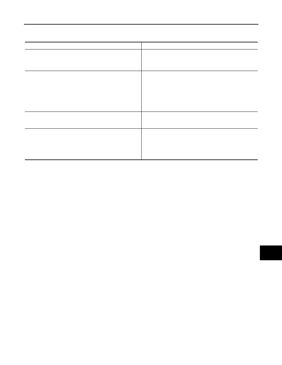
Component Description
INFOID:0000000009160045
Component part
Description
Battery current sensor
Battery current sensor is installed to the battery cable at the neg-
ative terminal, and it detects the charging/discharging current of
the battery and sends the voltage signal to ECM according to the
current value.
ECM
Battery current sensor detects the charging/discharging current of
the battery. ECM judges the battery condition based on this signal.
ECM judges whether to perform the power generation voltage
variable control according to the battery condition.
When performing the power generation voltage variable control,
ECM calculates the target power generation voltage according to
the battery condition and sends the calculated value as the power
generation command value to IPDM E/R.
IPDM E/R
IPDM E/R converts the received power generation command val-
ue into the power generation command signal (PWM signal) and
sends it to the IC voltage regulator.
Alternator (IC voltage regulator)
IC voltage regulator controls the power generation voltage by the
target power generation voltage based on the received power gen-
eration command signal.
When there is no power generation command signal, the alterna-
tor performs the normal power generation according to the char-
acteristic of the IC voltage regulator.
Revision: 2012 November
2014 GT-R
CHG-6
< DTC/CIRCUIT DIAGNOSIS >
B TERMINAL CIRCUIT
DTC/CIRCUIT DIAGNOSIS
B TERMINAL CIRCUIT
Description
INFOID:0000000009160046
“B” terminal circuit supplies power to charge the battery and to operate the vehicle’s electrical system.
Diagnosis Procedure
INFOID:0000000009160047
1.
CHECK “B” TERMINAL CONNECTION
1.
Turn ignition switch OFF.
2.
Check if “B” terminal is clean and tight.
Is the inspection result normal?
YES
>> GO TO 2.
NO
>> Repair “B” terminal connection. Confirm repair by performing complete Charging system test
using EXP-800 NI or GR8-1200 NI (if available). Refer to the applicable Instruction Manual for
proper testing procedures.
2.
CHECK “B” TERMINAL CIRCUIT
Check voltage between alternator “B” terminal and ground.
Is the inspection result normal?
YES
>> GO TO 3.
NO
>> Check harness for open between alternator and fusible link.
3.
CHECK “B” TERMINAL CONNECTION (VOLTAGE DROP TEST)
1.
Start engine, then engine running at idle and warm.
2.
Check voltage between battery positive terminal and alternator “B” terminal.
Is the inspection result normal?
YES
>> “B” terminal circuit is normal.
NO
>> Check harness between battery and alternator for poor continuity.
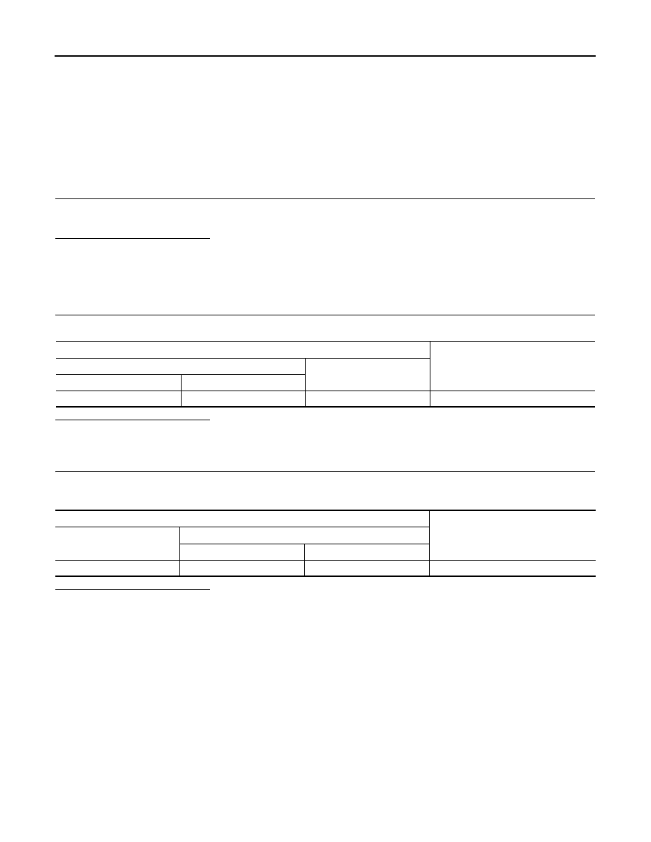
Terminals
Voltage (Approx.)
(+)
(–)
Alternator “B” terminal
Terminal
E254
1
Ground
Battery voltage
Terminals
Voltage (Approx.)
(+)
(–)
Alternator “B” terminal
Terminal
Battery positive terminal
E254
1
Less than 0.2 V
Revision: 2012 November
2014 GT-R
CHG
L TERMINAL CIRCUIT (OPEN)
CHG-7
< DTC/CIRCUIT DIAGNOSIS >
C
D
E
F
G
H
I
J
K
L
B
A
O
P
N
L TERMINAL CIRCUIT (OPEN)
Description
INFOID:0000000009160048
The “L” terminal circuit controls the charge warning lamp. The charge warning lamp illuminates when the igni-
tion switch is set to ON or START. When the alternator is providing sufficient voltage with the engine running,
the charge warning lamp will go off. If the charge warning lamp illuminates with the engine running, a malfunc-
tion is indicated.
Diagnosis Procedure
INFOID:0000000009160049
1.
CHECK “L” TERMINAL CONNECTION
1.
Turn ignition switch OFF.
2.
Check if “L” terminal is clean and tight.
Is the inspection result normal?
YES
>> GO TO 2.
NO
>> Repair “L” terminal connection. Confirm repair by performing complete Charging system test
using EXP-800 NI or GR8-1200 NI (if available). Refer to the applicable Instruction Manual for
proper testing procedures.
2.
CHECK “L” TERMINAL CIRCUIT (OPEN)
1.
Disconnect alternator connector.
2.
Apply ground to alternator harness connector terminal.
3.
Check condition of the charge warning lamp with the ignition switch in the ON position.
Does it illuminate?
YES
>> “L” terminal circuit is normal.
NO
>> GO TO 3.
3.
CHECK HARNESS CONTINUITY (OPEN CIRCUIT)
1.
Disconnect the battery cable from the negative terminal.
2.
Disconnect the combination meter connector.
3.
Check continuity between alternator harness connector and combination meter harness connector.
Is the inspection result normal?
YES
>> GO TO 4.
NO
>> Repair the harness or connector.
4.
CHECK HARNESS CONTINUITY (OPEN CIRCUIT)
Check continuity between combination meter harness connector and fuse block.
Is the inspection result normal?
YES
>> GO TO 5.
NO
>> Repair the harness.
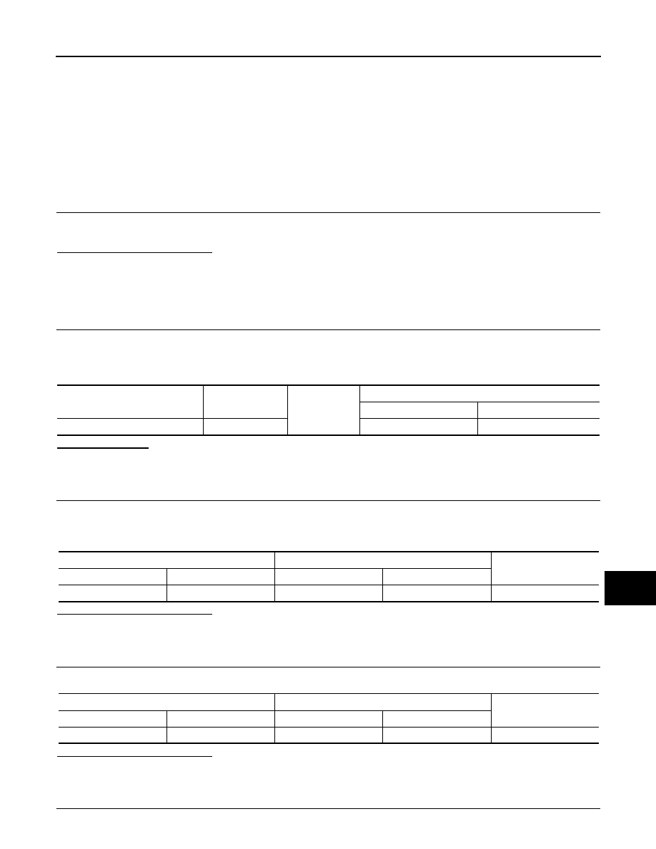
5.
CHECK POWER SUPPLY CIRCUIT
Alternator harness connector
Terminal
Ground
Condition
Ignition switch position
Charge warning lamp
E254
2
ON
Illuminate
Alternator harness connector
Combination meter harness connector
Continuity
Connector No.
Terminal No.
Connector No.
Terminal No.
E254
2
M53
28
Existed
Combination meter harness connector
Fuse block
Continuity
Connector No.
Terminal No.
Connector No.
Terminal No.
M53
2
M3
12C
Existed
Revision: 2012 November
2014 GT-R
CHG-8
< DTC/CIRCUIT DIAGNOSIS >
L TERMINAL CIRCUIT (OPEN)
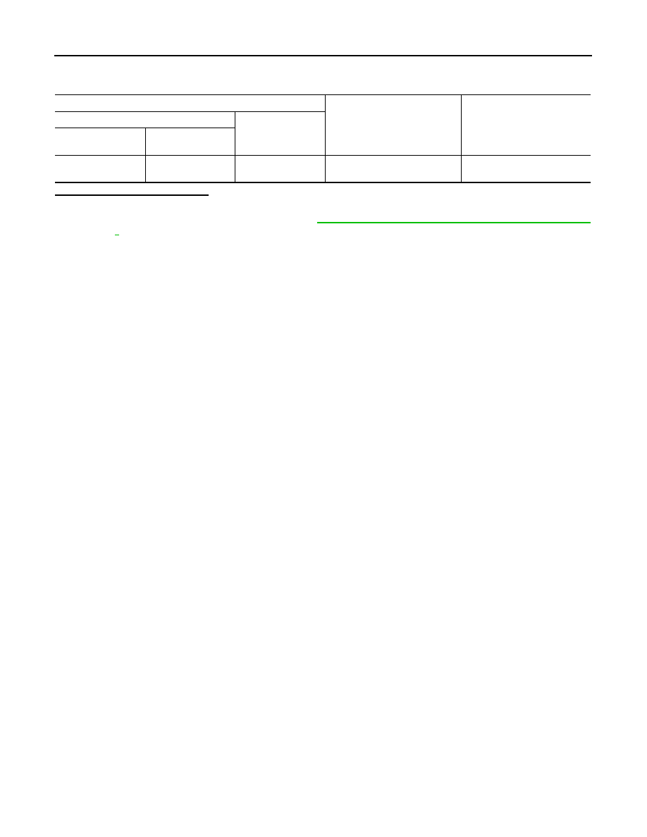
1.
Connect the battery cable to the negative terminal.
2.
Check voltage between combination meter harness connector and ground.
Is the inspection result normal?
YES
>> Replace combination meter.
NO
>> Inspect the power supply circuit. Refer to
PG-17, "Wiring Diagram - IGNITION POWER SUPPLY -
Terminals
Condition
Voltage (Approx.)
(+)
(–)
Combination meter
harness connector
Terminal
M53
2
Ground
When the ignition switch is in
ON position
Battery voltage
Revision: 2012 November
2014 GT-R
CHG
CHARGING SYSTEM
CHG-9
< DTC/CIRCUIT DIAGNOSIS >
C
D
E
F
G
H
I
J
K
L
B
A
O
P
N
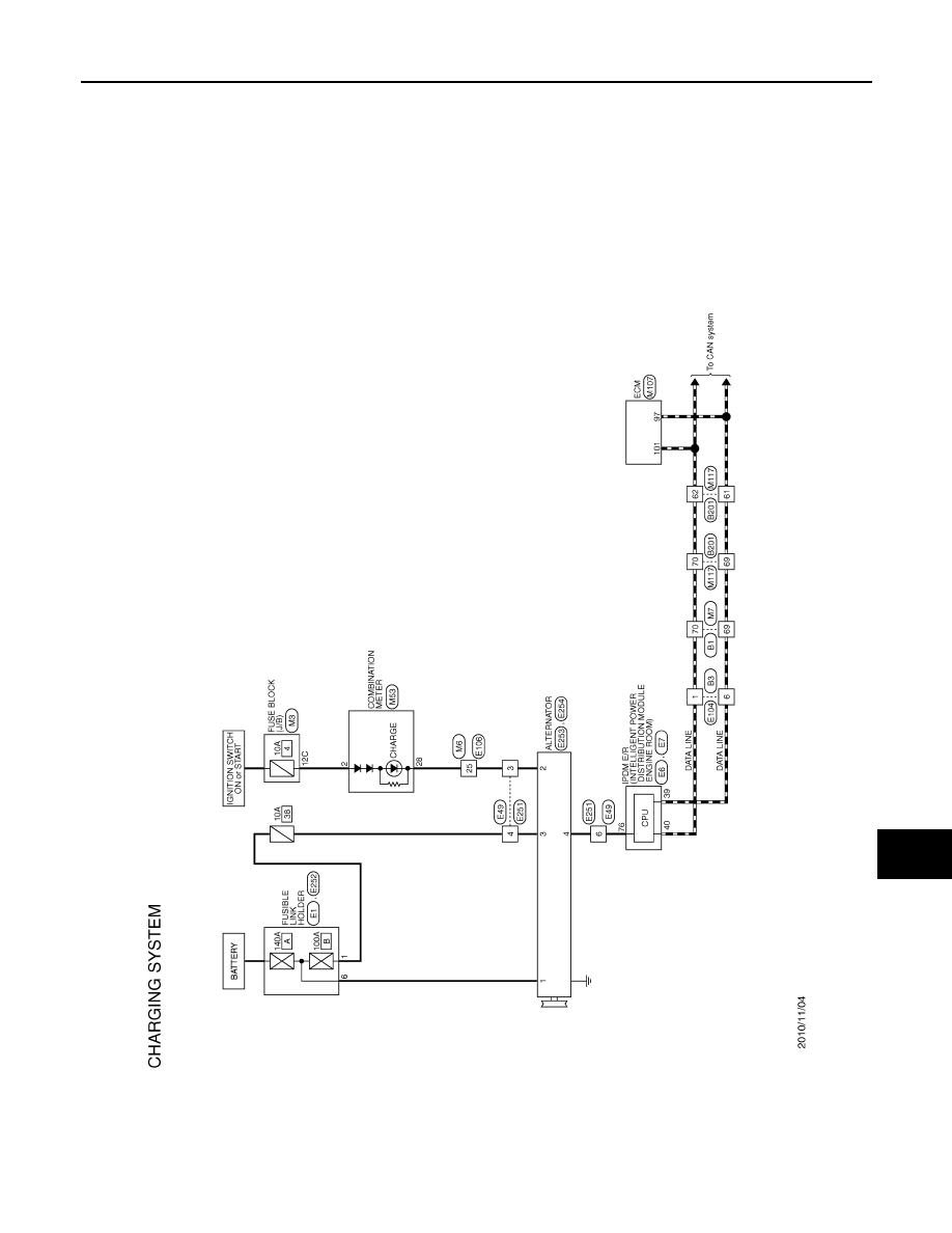
CHARGING SYSTEM
Wiring Diagram - CHARGING SYSTEM -
INFOID:0000000009160054
JCMWA6844GB
Revision: 2012 November
2014 GT-R
CHG-10
< PRECAUTION >
PRECAUTIONS
PRECAUTION
PRECAUTIONS
Precaution for Working Range at a Regular Dealership
INFOID:0000000009166612
CAUTION:
The service items unmentioned on this manual are recommended to be performed by a GT-R certified
NISSAN dealer. Because those service items require special equipment and a GT-R certified technical
staff who completed special training.
Precaution for Supplemental Restraint System (SRS) "AIR BAG" and "SEAT BELT
PRE-TENSIONER"
INFOID:0000000009160056
The Supplemental Restraint System such as “AIR BAG” and “SEAT BELT PRE-TENSIONER”, used along
with a front seat belt, helps to reduce the risk or severity of injury to the driver and front passenger for certain
types of collision. This system includes seat belt switch inputs and dual stage front air bag modules. The SRS
system uses the seat belt switches to determine the front air bag deployment, and may only deploy one front
air bag, depending on the severity of a collision and whether the front occupants are belted or unbelted.
Information necessary to service the system safely is included in the “SRS AIR BAG” and “SEAT BELT” of this
Service Manual.
WARNING:
Always observe the following items for preventing accidental activation.
• To avoid rendering the SRS inoperative, which could increase the risk of personal injury or death in
the event of a collision that would result in air bag inflation, all maintenance must be performed by
an authorized NISSAN/INFINITI dealer.
• Improper maintenance, including incorrect removal and installation of the SRS, can lead to personal
injury caused by unintentional activation of the system. For removal of Spiral Cable and Air Bag
Module, see “SRS AIR BAG”.
• Never use electrical test equipment on any circuit related to the SRS unless instructed to in this Ser-
vice Manual. SRS wiring harnesses can be identified by yellow and/or orange harnesses or harness
connectors.
PRECAUTIONS WHEN USING POWER TOOLS (AIR OR ELECTRIC) AND HAMMERS
WARNING:
Always observe the following items for preventing accidental activation.
• When working near the Air Bag Diagnosis Sensor Unit or other Air Bag System sensors with the
ignition ON or engine running, never use air or electric power tools or strike near the sensor(s) with
a hammer. Heavy vibration could activate the sensor(s) and deploy the air bag(s), possibly causing
serious injury.
• When using air or electric power tools or hammers, always switch the ignition OFF, disconnect the
battery, and wait at least 3 minutes before performing any service.
Precautions Necessary for Steering Wheel Rotation After Battery Disconnection
INFOID:0000000009160057
CAUTION:
Comply with the following cautions to prevent any error and malfunction.
• Before removing and installing any control units, first turn the ignition switch to the LOCK position,
then disconnect both battery cables.
• After finishing work, confirm that all control unit connectors are connected properly, then re-connect
both battery cables.
• Always use CONSULT to perform self-diagnosis as a part of each function inspection after finishing
work. If a DTC is detected, perform trouble diagnosis according to self-diagnosis results.
For vehicle with steering lock unit, if the battery is disconnected or discharged, the steering wheel will lock and
cannot be turned.
If turning the steering wheel is required with the battery disconnected or discharged, follow the operation pro-
cedure below before starting the repair operation.
OPERATION PROCEDURE
1.
Connect both battery cables.
Revision: 2012 November
2014 GT-R
CHG
PRECAUTIONS
CHG-11
< PRECAUTION >
C
D
E
F
G
H
I
J
K
L
B
A
O
P
N
NOTE:
Supply power using jumper cables if battery is discharged.
2.
Turn the ignition switch to ACC position.
(At this time, the steering lock will be released.)
3.
Disconnect both battery cables. The steering lock will remain released with both battery cables discon-
nected and the steering wheel can be turned.
4.
Perform the necessary repair operation.
5.
When the repair work is completed, re-connect both battery cables. With the brake pedal released, turn
the ignition switch from ACC position to ON position, then to LOCK position. (The steering wheel will lock
when the ignition switch is turned to LOCK position.)
6.
Perform self-diagnosis check of all control units using CONSULT.
Precaution for Battery Service
INFOID:0000000009160058
Before disconnecting the battery, lower both the driver and passenger windows. This will prevent any interfer-
ence between the window edge and the vehicle when the door is opened/closed. During normal operation, the
window slightly raises and lowers automatically to prevent any window to vehicle interference. The automatic
window function will not work with the battery disconnected.
Precaution for Power Generation Voltage Variable Control System
INFOID:0000000009160059
CAUTION:
For this model, the battery current sensor that is installed to the battery cable at the negative terminal
measures the charging/discharging current of the battery, and performs various controls. If the electri-
cal component or the ground wire is connected directly to the battery terminal, the current other than
that being measured with the battery current sensor is charging to or discharging from the battery.
This condition causes the malfunction of the control, and then the battery discharge may occur. Do
not connect the electrical component or the ground wire directly to the battery terminal.
Revision: 2012 November
2014 GT-R
CHG-12
< PREPARATION >
PREPARATION
PREPARATION
PREPARATION
Special Service Tools
INFOID:0000000009160060
Commercial Service Tools
INFOID:0000000009160061
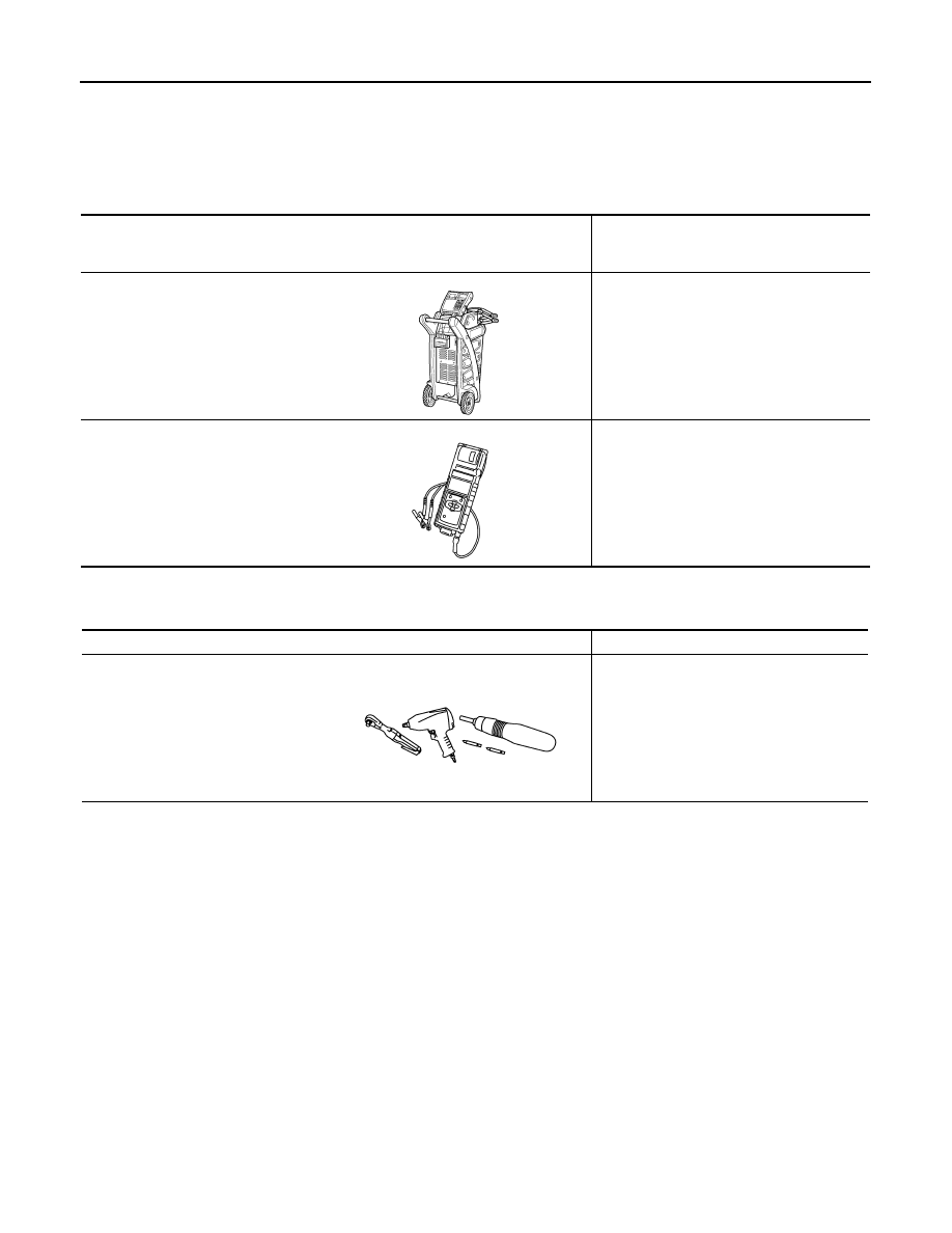
Tool number
(Kent-Moore No.)
Tool name
Description
—
(—) Model GR8-1200 NI
Multitasking battery and electrical di-
agnostic station
Tests batteries, starting and charging sys-
tems and charges batteries.
For operating instructions, refer to diagnos-
tic station instruction manual.
—
(—) Model EXP-800 NI
Battery and electrical diagnostic ana-
lyzer
Tests batteries and charging systems.
For operating instructions, refer to diagnos-
tic analyzer instruction manual.
AWIIA1239ZZ
JSMIA0806ZZ
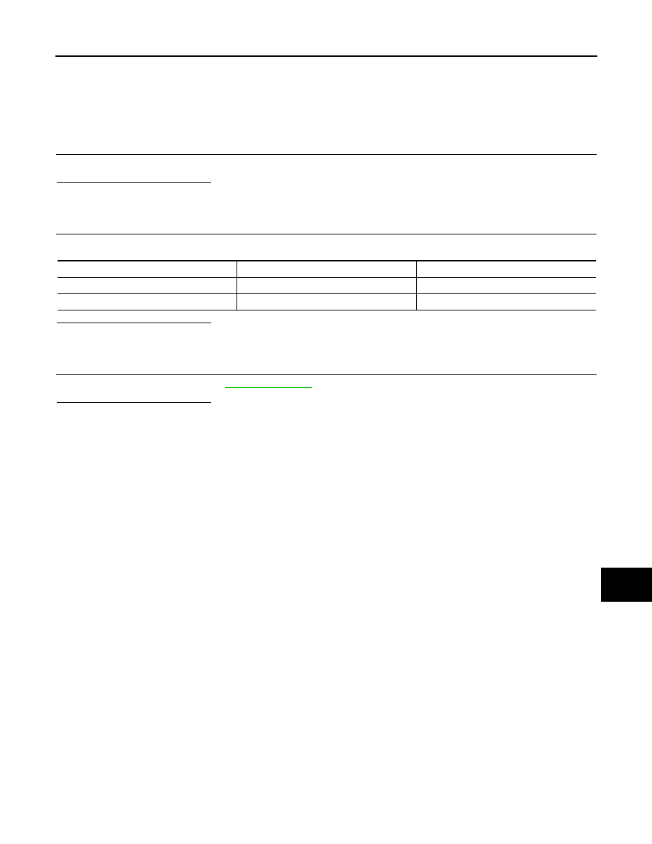
Tool name
Description
Power tool
Loosening bolts, nuts and screws
PIIB1407E
Revision: 2012 November
2014 GT-R
CHG
CHARGING SYSTEM PRELIMINARY INSPECTION
CHG-13
< PERIODIC MAINTENANCE >
C
D
E
F
G
H
I
J
K
L
B
A
O
P
N
PERIODIC MAINTENANCE
CHARGING SYSTEM PRELIMINARY INSPECTION
Inspection Procedure
INFOID:0000000009160062
1.
CHECK BATTERY TERMINALS CONNECTION
Check if battery terminals are clean and tight.
Is the inspection result normal?
YES
>> GO TO 2.
NO
>> Repair battery terminals connection.
2.
CHECK FUSE
Check for blown fuse and fusible link.
Is the inspection result normal?
YES
>> GO TO 3.
NO
>> Be sure to eliminate the cause of malfunction before installing new fuse.
3.
CHECK DRIVE BELT TENSION
Check drive belt tension. Refer to
.
Is the inspection result normal?
YES
>> INSPECTION END
NO
>> Repair as needed.
Unit
Power source (Power supply terminals)
Fuse No.
Alternator
Battery (“S” terminal)
38
Combination meter
Ignition switch ON (“L” terminal)
4
Revision: 2012 November
2014 GT-R

CHG-14
< SERVICE DATA AND SPECIFICATIONS (SDS)
SERVICE DATA AND SPECIFICATIONS (SDS)
SERVICE DATA AND SPECIFICATIONS (SDS)
SERVICE DATA AND SPECIFICATIONS (SDS)
Alternator
INFOID:0000000009160067
*: Adjustment range of power generation voltage variable control is 11.4 - 15.6 V.
Type
A002TX0091
MITSUBISHI make
Nominal rating
[V - A]
12 -150
Ground polarity
Negative
Minimum revolution under no-load (When 13.5 V is applied)
[rpm]
Less than 1,300
Hot output current (When 13.5 V is applied)
[A/rpm]
More than 57/1,500
More than 126/2,500
More than 152/5,000
Regulated output voltage
[V]
14.1 - 14.7
*
Revision: 2012 November
2014 GT-R
CCS-1
CRUISE CONTROL
& DRIVER ASSISTANCE
C
D
E
F
G
H
I
J
K
L
M
B
CCS
SECTION
CCS
N
P
A
CONTENTS
CRUISE CONTROL SYSTEM
ASCD
SYSTEM DESCRIPTION . . . . . . . ..
AUTOMATIC SPEED CONTROL DEVICE
(ASCD) . . . . . . . . . . . . . . . ...
Information . . . . . . . . . . . . . . . ....
Revision: 2012 November
2014 GT-R
CCS-2
< SYSTEM DESCRIPTION >
[ASCD]
AUTOMATIC SPEED CONTROL DEVICE (ASCD)
SYSTEM DESCRIPTION
AUTOMATIC SPEED CONTROL DEVICE (ASCD)
Information
INFOID:0000000009160129
Automatic Speed Control Device (ASCD) system is controlled by ECM.
Revision: 2012 November
2014 GT-R
Нет комментариевНе стесняйтесь поделиться с нами вашим ценным мнением.
Текст