Qashqai J11. Steering system. Service and Repair Manual
Qashqai J11. Steering system. Service and Repair Manual
ST-1
STEERING
C
D
E
F
H
I
J
K
L
M
SECTION
ST
A
B
ST
N
O
P
CONTENTS
STEERING SYSTEM
PRECAUTION . . . . . . . . . . . ...
PRECAUTIONS . . . . . . . . . . . . ...
Precautions for Removing Battery Terminal . . .....
Precaution Necessary for Steering Wheel Rota-
tion After Battery Disconnect . . . . . . . . .....
Service Notice or Precautions for Steering System
. ..
PREPARATION . . . . . . . . . . .
PREPARATION . . . . . . . . . . . . ...
Special Service Tools . . . . . . . . . . . ....
Commercial Service Tools . . . . . . . . . ....
SYMPTOM DIAGNOSIS . . . . . . . ...
NOISE, VIBRATION AND HARSHNESS
(NVH) TROUBLESHOOTING . . . . . . . .
NVH Troubleshooting Chart . . . . . . . . . ..
BASIC INSPECTION . . . . . . . . .
STEERING WHEEL . . . . . . . . . . ...
Inspection . . . . . . . . . . . . . . . . .
REMOVAL AND INSTALLATION . . . .
STEERING WHEEL . . . . . . . . . . ...
Exploded View . . . . . . . . . . . . . . ..
Removal and Installation . . . . . . . . . . ..
STEERING COLUMN . . . . . . . . . .
Exploded View . . . . . . . . . . . . . . .
Removal and Installation . . . . . . . . . . .
Inspection . . . . . . . . . . . . . . . .
STEERING GEAR AND LINKAGE . . . . ...
Exploded View . . . . . . . . . . . . . . .
Removal and Installation . . . . . . . . . . .
Disassembly and Assembly . . . . . . . . . .
Inspection . . . . . . . . . . . . . . . .
SERVICE DATA AND SPECIFICATIONS
(SDS) . . . . . . . . . . . . . . .
SERVICE DATA AND SPECIFICATIONS
(SDS) . . . . . . . . . . . . . . . . .
ST-2
< PRECAUTION >
PRECAUTIONS
PRECAUTION
PRECAUTIONS
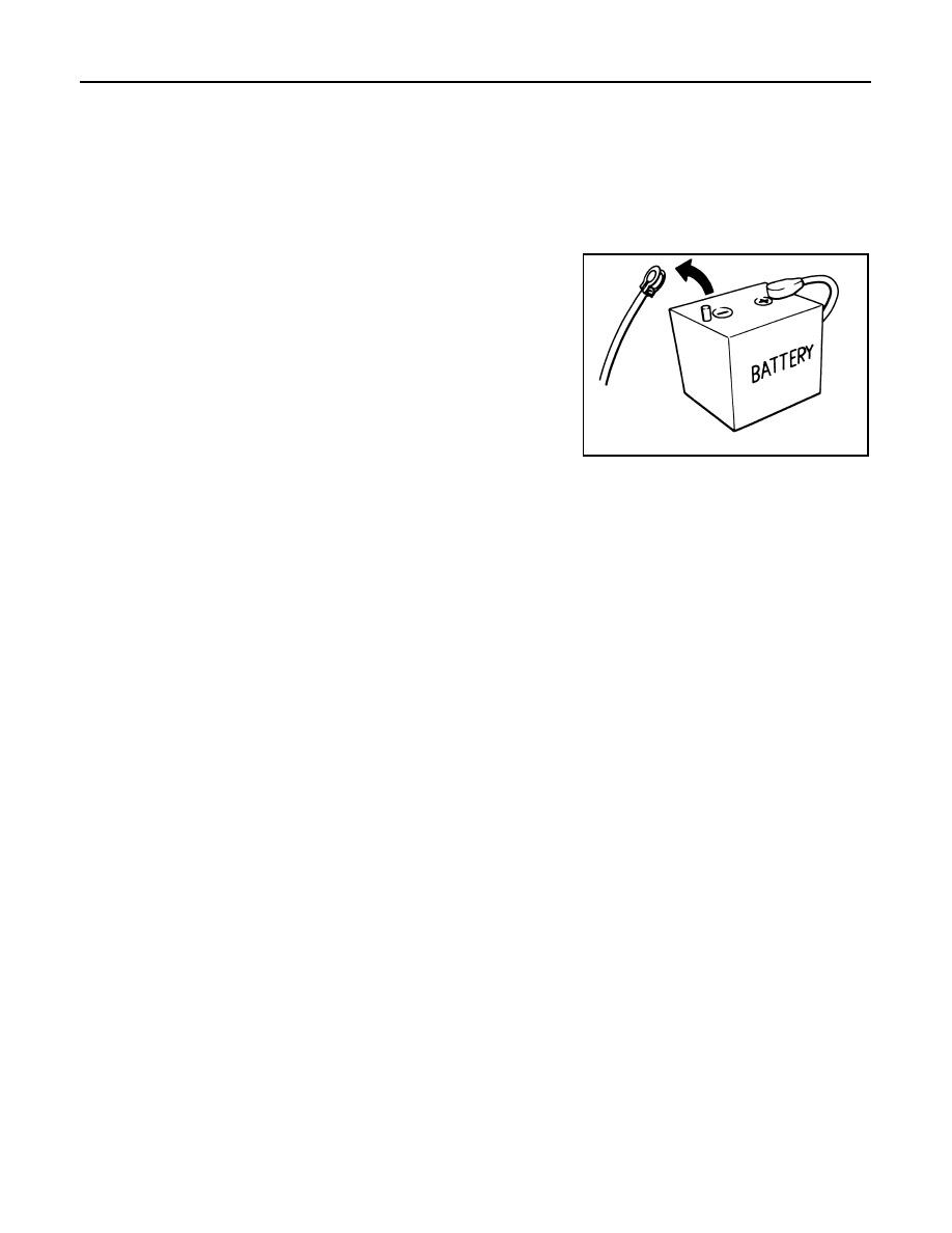
Precautions for Removing Battery Terminal
• With the adoption of Auto ACC function, ACC power is automatically supplied by operating the intelligent key
or remote keyless entry or by opening/closing the driver side door. In addition, ACC power is supplied even
after the ignition switch is turned to the OFF position, i.e. ACC power is supplied for a certain fixed time.
• When disconnecting the 12V battery terminal, turn off the ACC
power before disconnecting the 12V battery terminal, observing
“How to disconnect 12V battery terminal” described below.
NOTE:
Some ECUs operate for a certain fixed time even after ignition
switch is turned OFF and ignition power supply is stopped. If the
battery terminal is disconnected before ECU stops, accidental DTC
detection or ECU data damage may occur.
• For vehicles with the 2-batteries, be sure to connect the main bat-
tery and the sub battery before turning ON the ignition switch.
NOTE:
If the ignition switch is turned ON with any one of the terminals of
main battery and sub battery disconnected, then DTC may be detected.
• After installing the 12V battery, always check "Self Diagnosis Result" of all ECUs and erase DTC.
NOTE:
The removal of 12V battery may cause a DTC detection error.
HOW TO DISCONNECT 12V BATTERY TERMINAL
Disconnect 12V battery terminal according to Instruction 1 or Instruction 2 described below.
For vehicles parked by ignition switch OFF, refer to Instruction 2.
INSTRUCTION 1
1.
Open the hood.
2.
Turn key switch to the OFF position with the driver side door opened.
3.
Get out of the vehicle and close the driver side door.
4.
Wait at least 3 minutes. For vehicle with the engine listed below, remove the battery terminal after a lapse
of the specified time.
CAUTION:
While waiting, never operate the vehicle such as locking, opening, and closing doors. Violation of
this caution results in the activation of ACC power supply according to the Auto ACC function.
5.
Remove 12V battery terminal.
CAUTION:
After installing 12V battery, always check self-diagnosis results of all ECUs and erase DTC.
INSTRUCTION 2 (FOR VEHICLES PARKED BY IGNITION SWITCH OFF)
1.
Unlock the door with intelligent key or remote keyless entry.
NOTE:
At this moment, ACC power is supplied.
2.
Open the driver side door.
3.
Open the hood.
4.
Close the driver side door.
5.
Wait at least 3 minutes.
SEF289H
D4D engine
: 20 minutes
HRA2DDT
: 12 minutes
K9K engine
: 4 minutes
M9R engine
: 4 minutes
R9M engine
: 4 minutes
V9X engine
: 4 minutes
PRECAUTIONS
ST-3
< PRECAUTION >
C
D
E
F
H
I
J
K
L
M
A
B
ST
N
O
P
CAUTION:
While waiting, never operate the vehicle such as locking, opening, and closing doors. Violation of
this caution results in the activation of ACC power supply according to the Auto ACC function.
6.
Remove 12V battery terminal.
CAUTION:
After installing 12V battery, always check self-diagnosis results of all ECUs and erase DTC.
Precaution for Supplemental Restraint System (SRS) "AIR BAG" and "SEAT BELT
PRE-TENSIONER"
INFOID:0000000010502282
The Supplemental Restraint System such as “AIR BAG” and “SEAT BELT PRE-TENSIONER”, used along
with a front seat belt, helps to reduce the risk or severity of injury to the driver and front passenger for certain
types of collision. Information necessary to service the system safely is included in the “SRS AIR BAG” and
“SEAT BELT” of this Service Manual.
WARNING:
Always observe the following items for preventing accidental activation.
• To avoid rendering the SRS inoperative, which could increase the risk of personal injury or death in
the event of a collision that would result in air bag inflation, all maintenance must be performed by
an authorized NISSAN/INFINITI dealer.
• Improper maintenance, including incorrect removal and installation of the SRS, can lead to personal
injury caused by unintentional activation of the system. For removal of Spiral Cable and Air Bag
Module, see “SRS AIR BAG”.
• Never use electrical test equipment on any circuit related to the SRS unless instructed to in this Ser-
vice Manual. SRS wiring harnesses can be identified by yellow and/or orange harnesses or harness
connectors.
PRECAUTIONS WHEN USING POWER TOOLS (AIR OR ELECTRIC) AND HAMMERS
WARNING:
Always observe the following items for preventing accidental activation.
• When working near the Air Bag Diagnosis Sensor Unit or other Air Bag System sensors with the
ignition ON or engine running, never use air or electric power tools or strike near the sensor(s) with
a hammer. Heavy vibration could activate the sensor(s) and deploy the air bag(s), possibly causing
serious injury.
• When using air or electric power tools or hammers, always switch the ignition OFF, disconnect the
battery, and wait at least 3 minutes before performing any service.
Precaution Necessary for Steering Wheel Rotation After Battery Disconnect
INFOID:0000000010508842
CAUTION:
Comply with the following cautions to prevent any error and malfunction.
• Before removing and installing any control units, first turn the ignition power source and accessory
power source to the OFF, then disconnect both battery cables.
• After finishing work, confirm that all control unit connectors are connected properly, then re-connect
both battery cables.
• Always use CONSULT to perform self-diagnosis as a part of each function inspection after finishing
work. If a DTC is detected, perform trouble diagnosis according to self-diagnosis results.
For vehicle with steering lock unit, if the battery is disconnected or discharged, the steering wheel will lock and
cannot be turned.
If turning the steering wheel is required with the battery disconnected or discharged, follow the operation pro-
cedure below before starting the repair operation.
OPERATION PROCEDURE
1.
Connect both battery cables.
NOTE:
Supply power using jumper cables if battery is discharged.
2.
Open driver door.
3.
Turn the ignition switch to the ON position.
(At this time, the steering lock will be released.)
4.
Turn the ignition switch to OFF position with driver door open.
ST-4
< PRECAUTION >
PRECAUTIONS
5.
Wait for 3 minutes or longer with driver door open.
NOTE:
• Do not close driver door because the steering wheel locks when driver door is closed.
• The auto acc function is adapted to this vehicle. For this reason, even when the ignition switch is turned
to OFF position, the accessory power source does not turned OFF and continues to be supplied for a
certain amount of time.
6.
Disconnect both battery cables. The steering lock will remain released with both battery cables discon-
nected and the steering wheel can be turned.
7.
Perform the necessary repair operation.
8.
When the repair work is completed, re-connect both battery cables. With the brake pedal released, turn
the ignition switch from OFF position to ON position, then to LOCK position. (The steering wheel will lock
when the ignition switch is turned to LOCK position.)
9.
Perform self-diagnosis check of all control units using CONSULT.
Service Notice or Precautions for Steering System
INFOID:0000000010502284
• In case of removing steering gear assembly, make the final tightening with grounded and unloaded vehicle
condition, and then check wheel alignment.
• Observe the following precautions when disassembling.
- Before disassembly, thoroughly clean the outside of the unit.
- Disassembly should be done in a clean work area. It is important to prevent the internal parts from becoming
contaminated by dirt or other foreign matter.
- For easier and proper assembly, place disassembled parts in order on a parts rack.
- Use nylon cloth or paper towels to clean the parts; common shop rags can leave lint that might interfere with
their operation.
- Never reuse non-reusable parts.
- Before assembling, apply the specified grease to the directed parts.
• During quick steering, rasping noise may be heard from around the steering wheel. This is not a malfunction.
The noise is an operating noise of the EPS system under normal conditions. If the rasping noise occurs dur-
ing slow steering, this may not be an operating noise of the system. In this case, it is necessary to find out
the location of the noise and repair, if necessary.
• Never repeat static steering. (Motor and EPS control unit could be heated.)
PREPARATION
ST-5
< PREPARATION >
C
D
E
F
H
I
J
K
L
M
A
B
ST
N
O
P
PREPARATION
PREPARATION
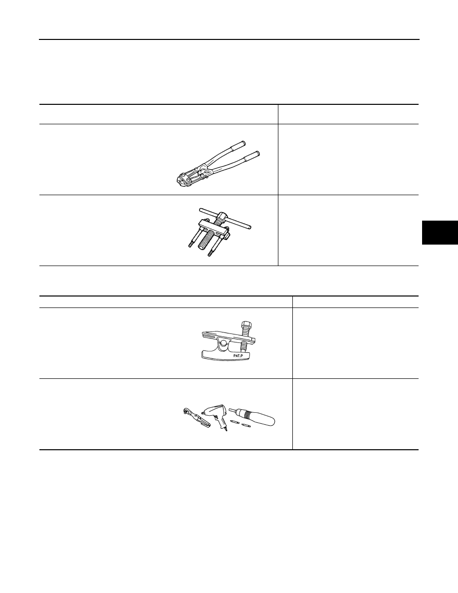
Special Service Tools
INFOID:0000000010438958
The actual shape of the tools may differ from those illustrated here.
Commercial Service Tools
INFOID:0000000010438959
Tool number
Tool name
Description
KV40107300
Boot Band crimping tool
Installing boot bands (large diameter)
ST27180001
Steering wheel puller
Removing steering wheel
ZZA1229D
ZZA0819D
Tool name
Description
Ball joint remover
Removing ball joint
Power tool
Loosening nuts, screws and bolts
NT146
PIIB1407E
ST-6
< SYMPTOM DIAGNOSIS >
NOISE, VIBRATION AND HARSHNESS (NVH) TROUBLESHOOTING
SYMPTOM DIAGNOSIS
NOISE, VIBRATION AND HARSHNESS (NVH) TROUBLESHOOTING
NVH Troubleshooting Chart
INFOID:0000000010438960
Use the chart below to find the cause of the symptom. If necessary, repair or replace these parts.
×
: Applicable
Reference
—
—
—
—
—
—
—
—
—
—
—
—
Possible cause and SUSPECTED PARTS
Ou
te
r/in
ne
r so
ck
et
ba
ll jo
int
swi
n
g
in
g
to
rqu
e
Ou
te
r/in
ne
r so
cket
ba
ll jo
int
rot
a
ti
ng
to
rqu
e
Ou
te
r/in
ne
r so
ck
et
ba
ll jo
int
en
d
pla
y
S
tee
ri
ng
wh
e
e
l p
lay
Imp
rop
er s
te
e
ri
ng
whe
e
l
Im
pro
p
e
r in
st
al
la
ti
on
o
r lo
os
en
es
s o
f t
ilt
lo
ck
l
e
ve
r
M
o
u
n
ti
ng
lo
os
en
es
s
S
te
e
rin
g
co
lum
n
de
form
a
tio
n o
r da
m
age
Im
pro
p
e
r in
st
al
la
ti
on
o
r lo
os
en
es
s o
f s
te
e
ri
ng
co
lu
mn
S
te
e
rin
g
lin
ka
ge
lo
os
en
es
s
PROP
ELLER SHAFT
(A
WD)
D
IFFERENTIAL (A
WD)
SUSPENSION
AXLE
WHEEL AND
TIRE
D
R
IVE SHAF
T
BRAKE
Symptom
Steering
Noise
×
×
×
×
×
×
×
×
×
×
×
×
×
Shake
×
×
×
×
×
×
×
×
×
Vibration
×
×
×
×
×
×
×
×
×
Shimmy
×
×
×
×
×
×
×
Shudder
×
×
×
×
×
×
×
STEERING WHEEL
ST-7
< BASIC INSPECTION >
C
D
E
F
H
I
J
K
L
M
A
B
ST
N
O
P
BASIC INSPECTION
STEERING WHEEL
Inspection
INFOID:0000000010438961
NEUTRAL POSITION STEERING WHEEL
1.
Check that steering gear assembly, steering column assembly and steering wheel are installed in the cor-
rect position.
2.
Check wheel alignment within specification. Refer to
FSU-7, "Wheel Alignment Inspection"
.
3.
Set vehicle to the straight-ahead position and confirm steering wheel is in the neutral position.
• Loosen outer socket lock nut and turn inner socket to left and right equally to make fine adjustments if
steering wheel is not in the neutral position.
CAUTION:
If the adjustment is performed by using the inner socket, check wheel alignment after the adjust-
ment. Refer to

ST-8
< REMOVAL AND INSTALLATION >
STEERING WHEEL
REMOVAL AND INSTALLATION
STEERING WHEEL
Exploded View
INFOID:0000000010438964
Removal and Installation
INFOID:0000000010438965
REMOVAL
NOTE:
When reconnecting spiral cable, fix cable with a tape so that fixing case and rotating part keep aligned. This
will omit neutral position alignment procedure during spiral cable installation.
1.
Set vehicle to the straight-ahead position.
2.
Remove driver air bag module. Refer to
SR-14, "Removal and Installation"
.
3.
Remove steering wheel bolt after steering is locked.
CAUTION:
Never reuse steering wheel lock bolt.
4.
Disconnect harness connector.
1.
Steering wheel
Refer to
for symbols in the figure.
AWGIA0318ZZ
STEERING WHEEL
ST-9
< REMOVAL AND INSTALLATION >
C
D
E
F
H
I
J
K
L
M
A
B
ST
N
O
P
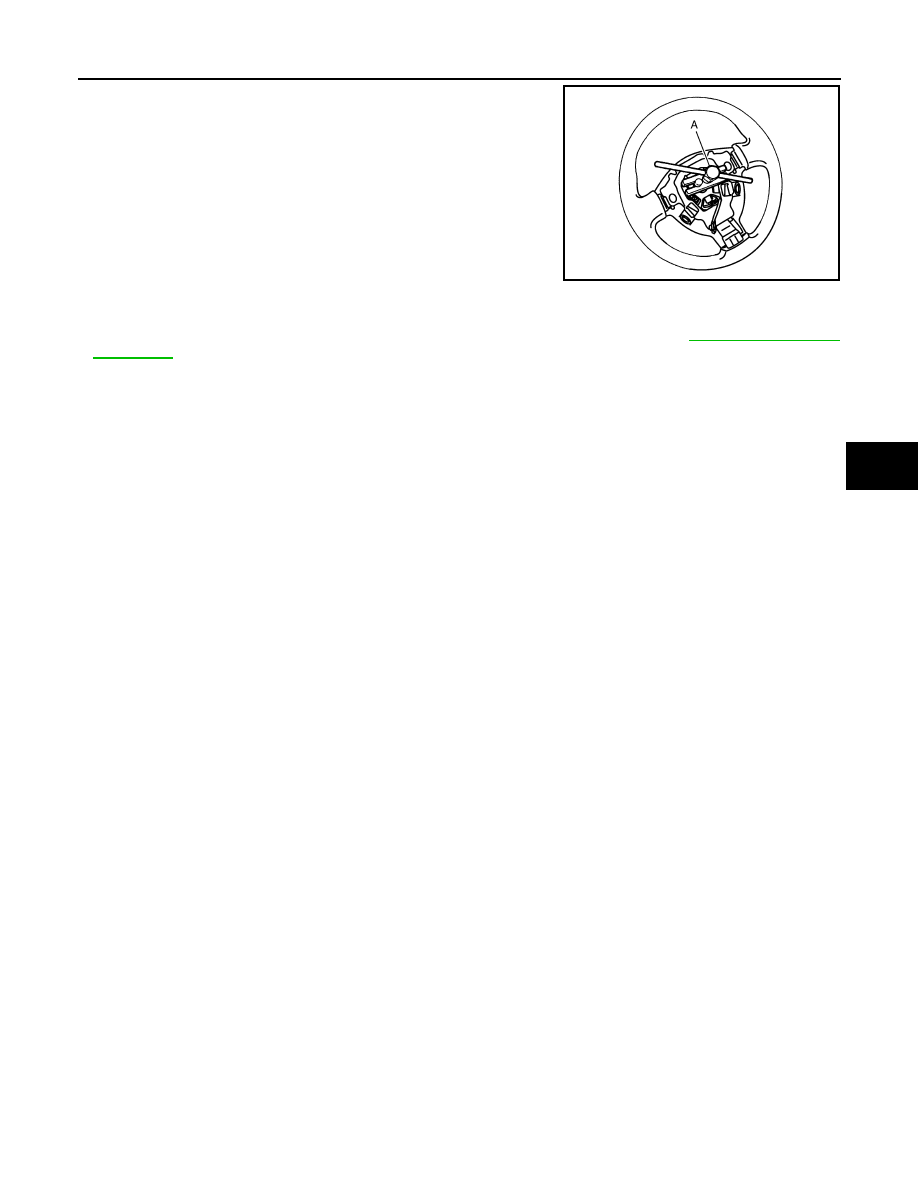
5.
Remove steering wheel with the steering wheel puller (A) (SST:
ST27180001).
INSTALLATION
Note the following, and install in the reverse order of removal.
• Check the spiral cable neutral position after replacing or rotating spiral cable. Refer to
.
CAUTION:
• Never twist spiral cable excessively after it becomes tight. (Twisting may cause the cable to be torn
off.)
• Never reuse steering wheel lock bolt.
SGIA1524J
ST-10
< REMOVAL AND INSTALLATION >
STEERING COLUMN
STEERING COLUMN
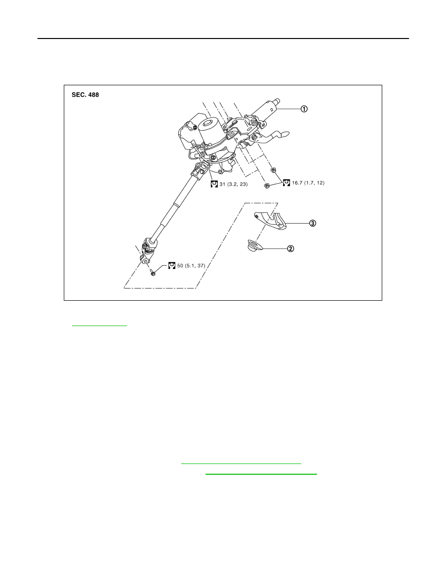
Exploded View
INFOID:0000000010438966
Removal and Installation
INFOID:0000000010438967
CAUTION:
• While removing the steering column assembly, never unlock the tilt lever.
• Never impact on the axis when removing steering column assembly.
• Be careful when removing steering column assembly from the vehicle because it is heavy.
• Keep steering column assembly away from magnetic sources.
• Never disassemble steering column assembly. It is not separable.
• While removing the steering column assembly, never move the steering gear.
• When removing the steering column assembly, be careful not to allow the intermediate shaft to turn.
REMOVAL
1.
Set vehicle to the straight-ahead position.
2.
Place the tilt to the highest level.
3.
Remove combination switch. Refer to
MWI-80, "Removal and Installation"
4.
Remove instrument lower panel LH. Refer to
IP-13, "Removal and Installation"
.
5.
Disconnect each switch harness connectors installed to steering column assembly.
6.
Remove bolt and separate steering column from steering gear pinion shaft.
CAUTION:
Never move the steering gear during removal and installation of the steering column.
7.
Remove nuts and remove steering column.
INSTALLATION
Installation is in the reverse order of removal.
CAUTION:
1.
Steering column
2.
Floor cover
3.
Floor seal
Refer to
for symbols in the figure.
E1GIA0093GB
STEERING COLUMN
ST-11
< REMOVAL AND INSTALLATION >
C
D
E
F
H
I
J
K
L
M
A
B
ST
N
O
P
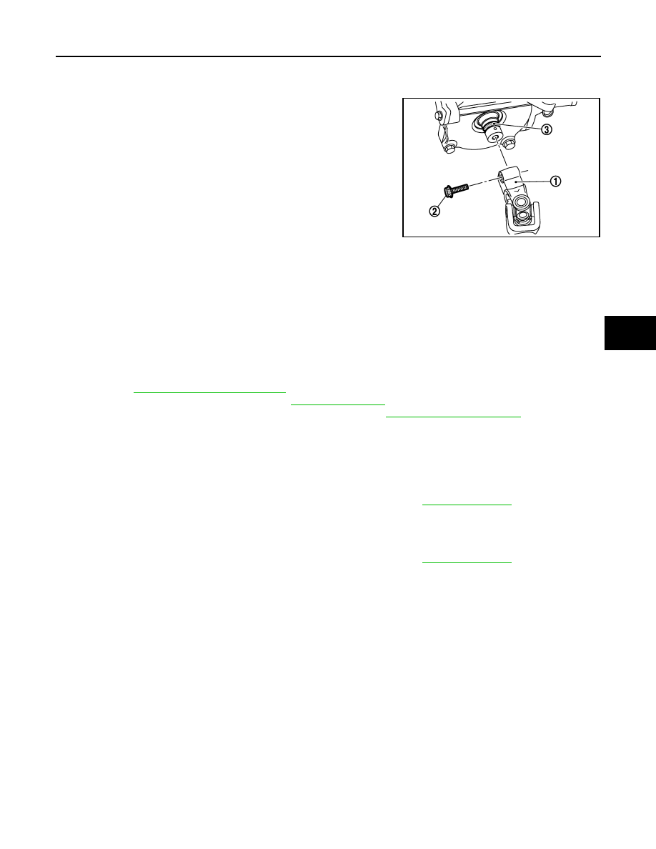
• When asembling the intermediate shaft upper joint (intermediate shaft to stteering column), always
use a new fixing bolt.
Align mark on intermediate shaft with mark on steering column.
• When installing the intermediate shaft upper joint (1), check
that the intermediate shaft upper joint fixing bolt (2) fits into
the groove (3)
• When installing the steering column, finger-tighten all of the lower bracket and joint retaining bolts;
then tighten them to specification. Do not apply undue stress to the steering column.
• Replace the steering column if it has been droped or sustained an impact.
• After installation, turn steering wheel to make sure it moves smoothly while turning to the left and right stops.
Make sure the number of turns are the same from the straight-forward position to left and right stops. Make
sure that the steering wheel is in a neutral position when driving straight ahead.
• When installing steering column to steering member, install nut from front of vehicle.
• After installing the steering column, check the tilt mechanism for proper operation.
• After installing steering column assembly, perform self-diagnosis with CONSULT to ensure correct opera-
• Preform inspection after installation. Refer to
• Adjust the neutral position of the steering angle sensor. Refer to
Inspection
INFOID:0000000010438968
INSPECTION AFTER REMOVAL
• Check each part of steering column for damage or other malfunctions.
• Check if steering wheel turns smoothly when it is turned several times fully to the end of the left and right.
• Check the steering wheel play, neutral position steering wheel. Refer to
INSPECTION AFTER INSTALLATION
• Check each part of steering column for damage or other malfunctions.
• Check if steering wheel turns smoothly when it is turned several times fully to the end of the left and right.
• Check the steering wheel play, neutral position steering wheel. Refer to
E1GIA0014ZZ
ST-12
< REMOVAL AND INSTALLATION >
STEERING GEAR AND LINKAGE
STEERING GEAR AND LINKAGE
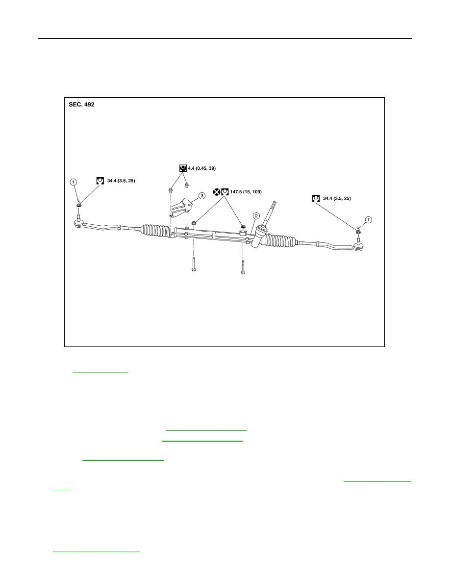
Exploded View
INFOID:0000000010438969
REMOVAL AND INSTALLATION
Removal and Installation
INFOID:0000000010438970
REMOVAL
1.
Set the front wheels and tires to the straight-ahead position.
2.
Remove the floor cover. Refer to
3.
Remove the floor seal. Refer to
.
4.
Remove the joint retaining bolt and separate the steering column yoke from the steering gear pinion shaft.
Refer to
5.
Remove the cotter pins (LH/RH), nuts (LH/RH) and disconnect the outer sockets (LH/RH).
6.
Separate the stabilizer connecting rods (LH/RH) from the stabilizer bar. Refer to
.
7.
Disconnect the harness connector for oxygen sensor 2.
8.
Remove the front exhaust tube.
9.
Remove the center exhaust tube.
10. Remove the lower torque rod.
11. Remove front suspension member stay and support the front suspension using a suitable jack. Refer to
1.
Cotter pin
2.
Steering gear
3.
Heat shield
Refer to
for symbols in the figure.
ALGIA0174ZZ
STEERING GEAR AND LINKAGE
ST-13
< REMOVAL AND INSTALLATION >
C
D
E
F
H
I
J
K
L
M
A
B
ST
N
O
P
12. Remove bolts and remove the steering gear.
INSTALLATION
Installation is in the reverse order of removal.
NOTE:
The torque must be applied to the nut on the upper side of the steering gear.
CAUTION:
• With the steering linkage disconnected, the spiral cable may snap by turning the steering wheel
beyond the limited number of turns.
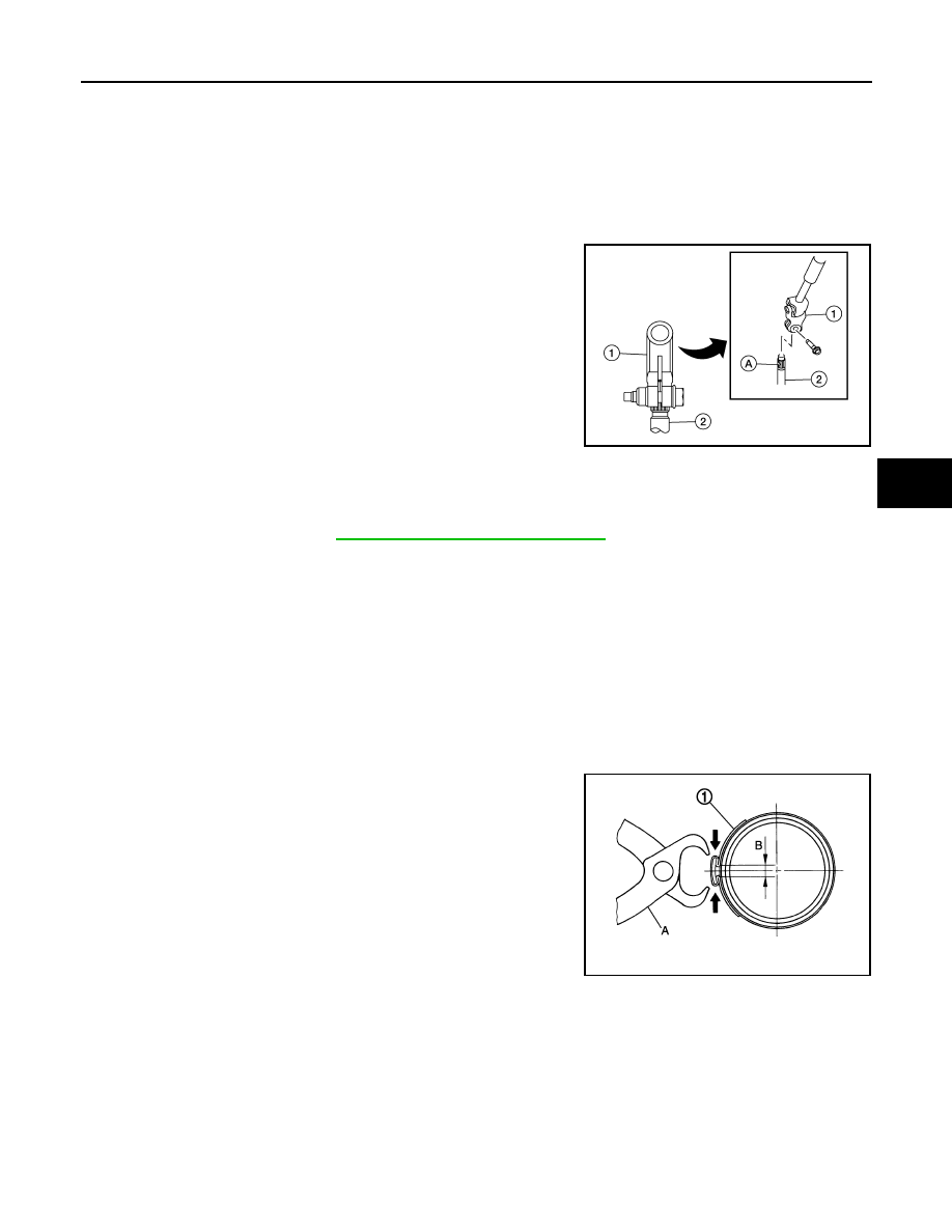
• When connecting the steering column yoke (1) to the steering
gear pinion shaft (2), be sure that gap (A) lines up with the
joint retaining bolt hole.
• When installing the steering column, finger-tighten all of the lower bracket and joint retaining bolts;
then tighten them to specification. Do not apply undue stress to the steering column.
• Do not reuse steering gear nuts.
• Check wheel alignment. Refer to
FSU-7, "Wheel Alignment Inspection"
.
• Adjust the neutral position of the steering angle sensor.
Disassembly and Assembly
INFOID:0000000010478068
DISASSEMBLY
1.
Remove outer socket lock nut and remove outer socket.
2.
Remove inner and outer boot clamps and remove boot.
ASSEMBLY
1.
Apply recommended grease to inner socket.
2.
Install boot to steering gear.
3.
Install inner boot clamp (1) to boot and secure using Tool (A).
CAUTION:
• Install inner boot clamp (1) securely to boot groove, and
crimp it so as to have clearance (B) of 3 mm (0.12 in) or
less as shown.
• Inspect boot clamps and replace as necessary.
4.
Install outer boot clamp to boot.
CAUTION:
Inspect boot and replace as necessary.
AWGIA0320ZZ
Tool number
: (KV40107300) (
—
)
JSGIA0140ZZ
ST-14
< REMOVAL AND INSTALLATION >
STEERING GEAR AND LINKAGE
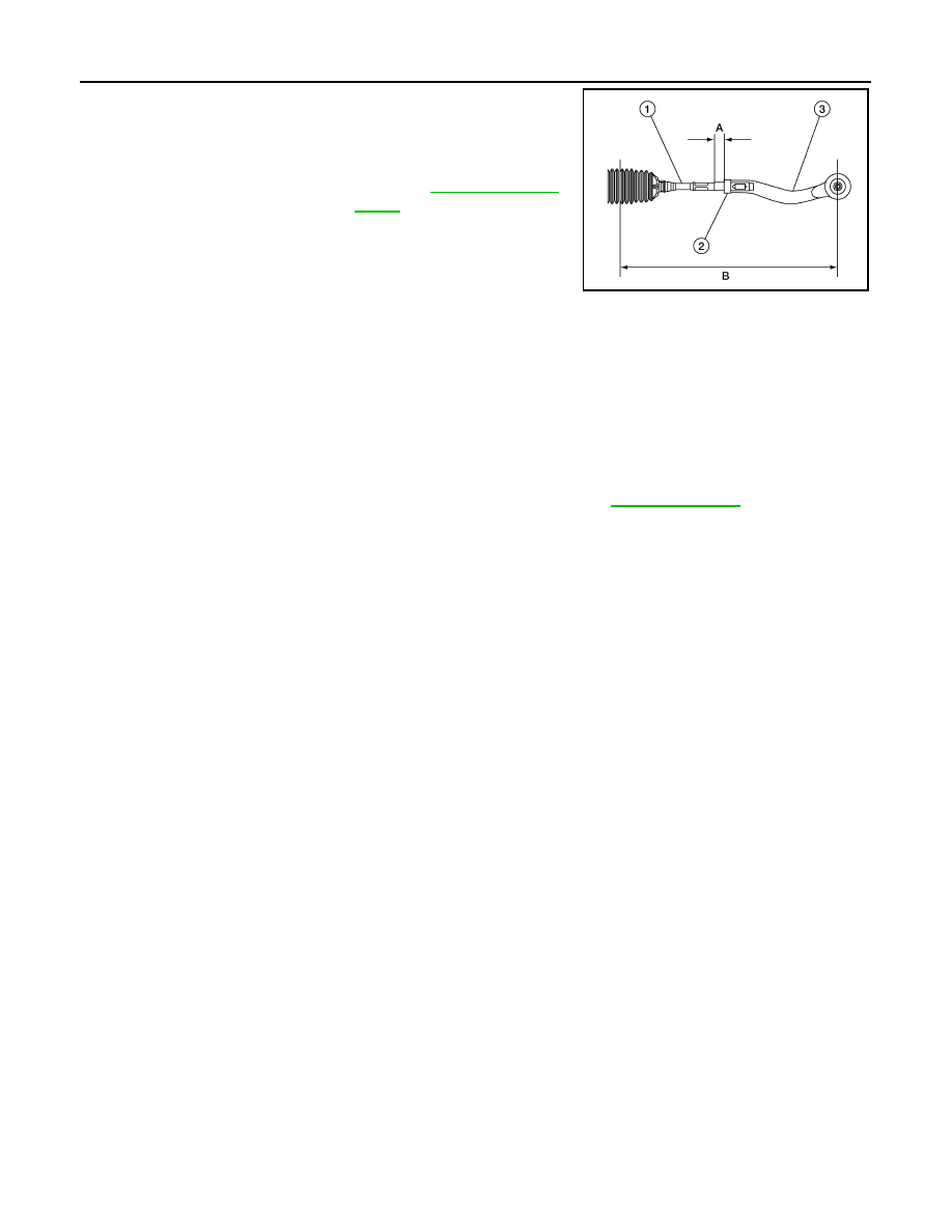
5.
Install outer socket (3) and lock nut (2) to achieve length (A).
Check that inner socket (1) and outer socket (3) measure to
standard length (B), then tighten lock nut (2) to the specified
torque. Check length again after tightening lock nut (2).
CAUTION:
• Dimension (A) must be less than 13 mm (0.51 in) after all wheel alignment adjustment.
• Dimension (B) is for reference and may change after toe in adjustment.
• When tightening lock nut, be sure to fix outer socket with a wrench or equivalent to prevent ball
joint from getting contact with knuckle.
Inspection
INFOID:0000000010438971
INSPECTION AFTER INSTALLATION
• Check if steering wheel turns smoothly when it is turned several times fully to the end of the left and right.
• Check the steering wheel play, neutral position steering wheel. Refer to
B
: Refer to
AWGIA0321ZZ
SERVICE DATA AND SPECIFICATIONS (SDS)
ST-15
< SERVICE DATA AND SPECIFICATIONS (SDS)
C
D
E
F
H
I
J
K
L
M
A
B
ST
N
O
P
SERVICE DATA AND SPECIFICATIONS (SDS)
SERVICE DATA AND SPECIFICATIONS (SDS)
Steering Gear
INFOID:0000000010438978
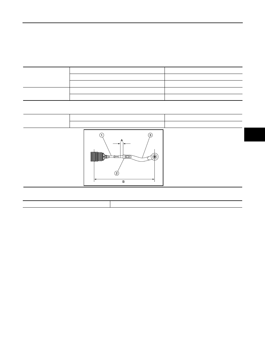
STEERING OUTER SOCKET AND INNER SOCKET
INNER AND OUTER SOCKET LENGTH
RACK SLIDING FORCE
Outer socket
Rocking torque
0.3 - 2.9 N·m (0.03 - 0.29 kg-m, 3.0 - 25 in-lb)
Rotating torque
0.3 - 2.0 N·m (0.03 - 0.2 kg-m, 3.0 - 18 in-lb)
Axial end play
0.4 mm (0.020 in) or less
Inner socket
Rocking torque
7.8 - 16.7 N·m (0.80 - 1.7 kg-m, 69 - 148 in-lb)
Axial end play
0.2 mm (0.008 in) or less
Inner and outer socket
length
A
13 mm (0.51 in)
B
362.1 mm (14.2 in)
AWGIA0321ZZ
Rack sliding force
115 - 175 N-f (11.7 - 17.9 kg-f, 25.9 - 39.3 lb-f)
Нет комментариевНе стесняйтесь поделиться с нами вашим ценным мнением.
Текст