Freightliner Business Class. Manual — part 14
25–01 Clutch Release Bearing
and Release Cross-Shaft
Lubricating
Clutch Release Bearing
CAUTION
Do not over-lubricate the release bearing. Over-
lubricating could contaminate the clutch internally,
causing clutch slippage and eventual clutch
failure.
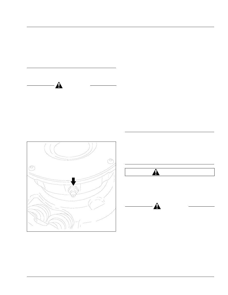
On clutches with a grease-type release bearing
(
), wipe the dirt from the grease fitting. Using a
pressure gun and high-temperature grease only, lu-
bricate the release bearing at the grease fitting until
the grease starts coming out of the fitting. Use only a
lithium-based grease that meets NLGI grade 1 or 2
specifications.
NOTE: On clutches with a sealed release bear-
ing, the release bearing is lubricated at the time
of manufacture and requires no additional
grease for the life of the bearing. This type of
release bearing is not equipped with a grease
fitting.
On Sachs hydraulic clutches, never lubricate the
release bearing. The release bearing is made of
plastic with a kind of embedded grease.
Clutch Release Cross-Shaft
The clutch release cross-shaft is equipped with two
grease fittings; one at each side of the transmission
clutch housing. Wipe the dirt from the grease fittings.
Using a pressure gun, lubricate the cross-shaft with
multipurpose chassis grease.
25–02 Clutch (Pull-Type)
Inspecting and
Adjusting
See Group 25 of the
Business Class
®
Trucks Ser-
vice Manual
for clutch (pull-type) inspecting and ad-
justing.
25–03 Hydraulic Fluid Level
Checking
WARNING
Use only approved DOT 3 brake fluid in the clutch
hydraulic system. Do not mix different types of
brake fluid. The wrong fluid will damage the rub-
ber parts of the system, causing loss of clutch
function and the risk of serious personal injury.
CAUTION
Do not allow the fluid level in the reservoir to go
below the MIN mark. If too much air enters, it will
not be possible to bleed the system properly, and
the clutch could be damaged.
If the fluid level is below the MIN mark, fill the reser-
voir with DOT 3 brake fluid until the level reaches the
MAX mark. See
f250081a
05/27/93
Fig. 1, Release Bearing Grease Fitting
Clutch
25
Business Class Trucks Maintenance Manual, June 2002
25/1
25–04 Hydraulic Fluid
Replacing
Replace the clutch hydraulic fluid every two years to
ensure clutch function is reliable and correct. Use the
procedures below. Fluid replacement must be done
at an authorized Freightliner service facility.
Draining and Filling
1.
Shut down the engine.
2.
Apply the parking brakes, chock the front and
rear tires, and open the hood.
WARNING
Clutch hydraulic fluid (DOT 3 brake fluid) is haz-
ardous. It may be a skin irritant and can cause
blindness if it gets in your eyes. Always wear
safety glasses when handling clutch hydraulic
fluid or bleeding hydraulic lines. If you get clutch
hydraulic fluid on your skin, wash it off as soon
as possible.
3.
Using a flat-head screwdriver, remove the quick-
disconnect clamp that attaches the hydraulic
hose to the slave cylinder. Retain the clamp for
later installation. See
06/17/2002
f250591
3
4
9
5
6
10
8
2
1
7
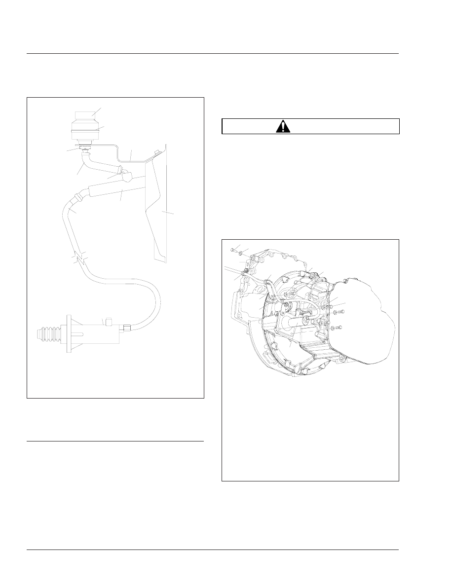
1.
Reservoir
2.
Reservoir Cap
3.
Reservoir Bracket
4.
Clutch Support Plate
5.
Master Cylinder
6.
Hydraulic Hose
7.
Slave Cylinder
8.
Elbow Connector
9.
Actuator Hose
10. Jam Nut
Fig. 2, Clutch Components
06/20/2002
f250592
1
2
3
4
5
4
6
7
8
9
10
11
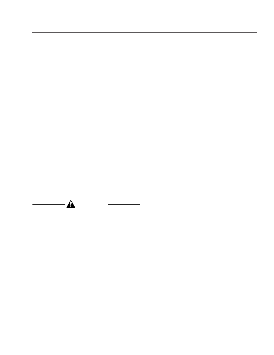
1.
Timing Case Mounting Capscrew, M10
2.
Hardened Flatwasher
3.
Timing Case Standoff Bracket
4.
Cushioned Clamp
5.
Bell Housing Standoff Bracket
6.
Hydraulic Hose
7.
Washer, M10
8.
Bell Housing-to-Timing Case Mounting Capscrew,
M10
9.
Flatwasher
10. Slave Cylinder Capscrew, M8
11. Slave Cylinder
Fig. 3, Clutch Slave Cylinder
Clutch
25
Business Class Trucks Maintenance Manual, June 2002
25/2
3.1
Using a drain pan or other suitable con-
tainer, collect the fluid that drains from the
pedal unit, not more than 0.3 quarts (0.3
liters).
3.2
Allow the open end of the drain hose to
remain over the drain pan.
3.3
Press down on the pedal several times,
until no more fluid drains from the reser-
voir in the pedal unit.
3.4
Cover the hose to avoid contamination of
the clutch hydraulic fluid.
4.
Connect the hydraulic hose to the slave cylinder.
Install the clamp, as removed.
5.
Fill the reservoir with approved DOT 3 brake fluid
and bleed the system according to the proce-
dures under the heading "Bleeding the Clutch."
See
Bleeding the Clutch
1.
Apply the parking brake and chock the tires.
2.
Prepare the pressure bleeding equipment ac-
cording to the manufacturer’s instructions. Use
DOT 3 brake fluid. Pressurize the bleeder unit to
15 psi (103 kPa).
CAUTION
Do not spill clutch hydraulic fluid (DOT 3 brake
fluid) on the cab paint. Clean it off immediately if
any is spilled. DOT 3 brake fluid can damage
paint.
3.
Remove the reservoir lid and install the pressure
bleed adaptor on the reservoir.
4.
Remove the cap from the bleed valve. Install a
transparent drain hose on the bleed valve of the
slave cylinder.
IMPORTANT: The slave cylinder may not be
mounted in a horizontal position. If it isn’t, re-
move the slave cylinder and hold it in a horizon-
tal position to completely purge all air from the
cylinder.
5.
Pressurize the reservoir, filling the system. Open
the bleed valve on the bleed tank.
NOTE: A pressure bleeder hose (J-29532) and
a bleeder adaptor (J-35798) for the fluid reser-
voir are available through SPX Kent-Moore
Tools and may be used to complete the follow-
ing procedure. To order these parts, call Kent-
Moore at 1-800-328-6657.
6.
Press the clutch pedal all the way down and
keep it down.
7.
Open the slave cylinder bleed valve. Observe the
flow of clutch hydraulic fluid through the drain
hose. When no bubbles appear in the fluid, close
the valve on the slave cylinder. Release the
clutch pedal and then close the valve at the
bleeder unit.
8.
Disconnect the bleeder unit, and install the cap
on the slave cylinder bleeder valve.
9.
Check the fluid level in the reservoir. If neces-
sary, add or remove clutch hydraulic fluid to bring
the fluid level to the MAX line. Install the reser-
voir cap.
10. Depress the clutch pedal a few times. There
should be resistance over the full pedal stroke.
11. Check the entire system for leaks. Tighten con-
nections if necessary. Check the fluid level in the
reservoir again.
12. Remove the chocks from the tires.
Clutch
25
Business Class Trucks Maintenance Manual, June 2002
25/3
06/20/2002
f250593
1
2
2
3
4
5
6
7
8
8
9
10
11
12
13
11
14
15
16
17
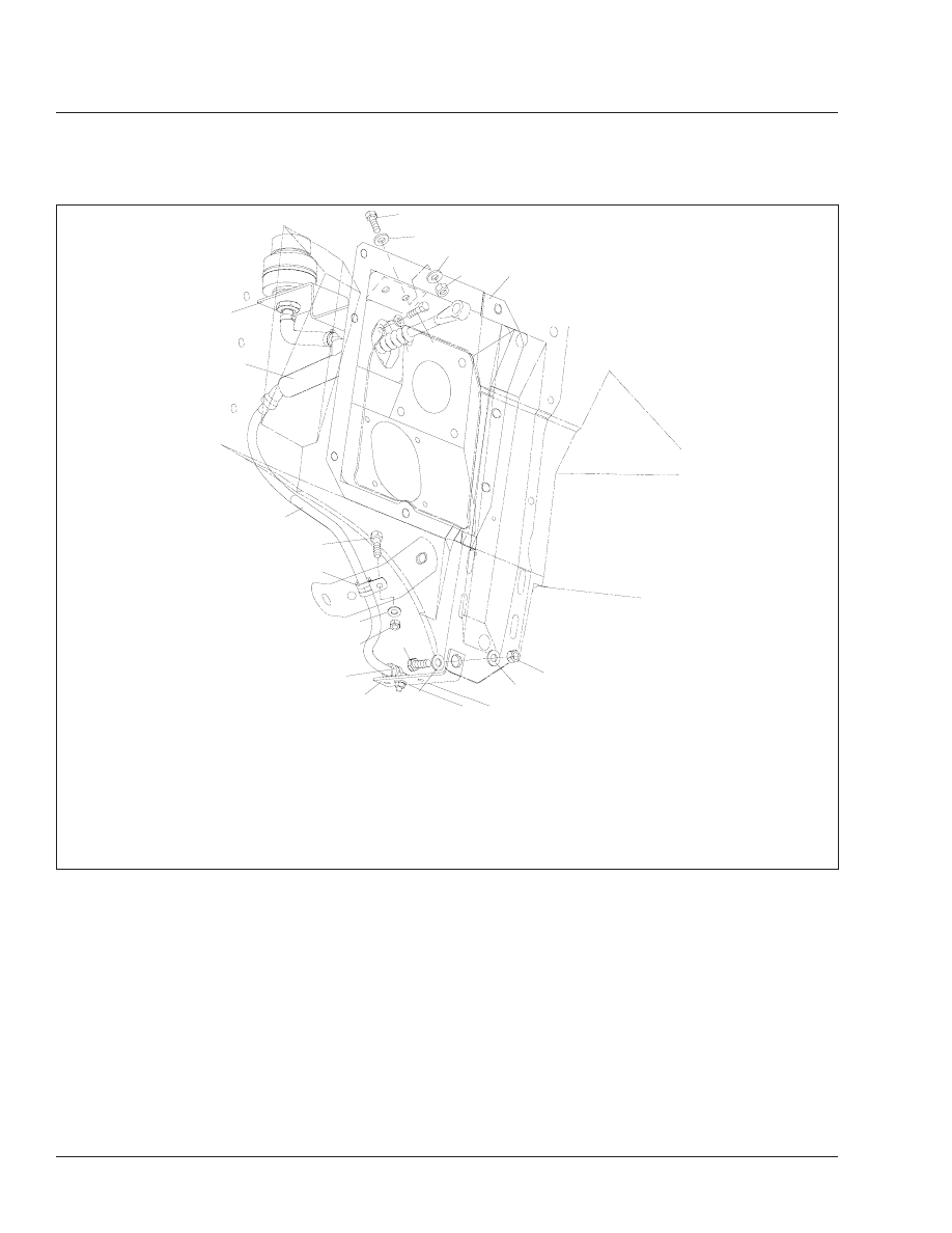
1.
Reservoir Bracket Mounting Bolt, 5/16–24
2.
Steel-Plated Washer, 5/16
3.
Locknut, 5/16–24
4.
Clutch Support Plate
5.
Master Cylinder Capscrew, M6
6.
Hardened Flatwasher, M6
7.
Locknut, 1/2–13
8.
Hardened Flatwasher, 0.53
9.
Frontwall Bracket Mounting Bolt, 1/2–13
10. Frontwall Standoff Bracket
11. Cushioned Clamp
12. Locknut, 1/4–20
13. Steel-Plated Washer, 1/4
14. Clamp Mounting Bolt, 1/4–20
15. Hydraulic Hose
16. Master Cylinder
17. Reservoir Bracket
Fig. 4, Clutch Master Cylinder
Clutch
25
Business Class Trucks Maintenance Manual, June 2002
25/4
Нет комментариевНе стесняйтесь поделиться с нами вашим ценным мнением.
Текст