Freightliner Business Class. Manual — part 34
3.5
Remove the hose from the test port, and
reconnect the gauge to the hose.
3.6
Install the protective plastic cap to the
pressure test port on the fuel rail.
3.7
Install the filler cap on the fuel tank.
4.
Disconnect the fuel supply line from the
filter/pressure regulator, then disconnect the
EVAP canister line from the rollover valve. See
5.
Disconnect the electrical connector.
6.
Remove the fuel pump module from the fuel
tank.
6.1
Clean the top of the fuel pump module to
prevent dirt from entering the fuel tank.
6.2
Remove the two capscrews holding the
fuel pump guard bracket in place. Re-
move the guard bracket, capscrews, and
hardened flatwashers.
6.3
Remove the other three capscrews hold-
ing the fuel pump clamp ring in place.
Remove the capscrews and hardened
flatwashers.
6.4
Remove the fuel pump module from the
fuel tank. See
6.5
Remove the fuel pump module gasket
from the fuel tank (see
) and dis-
card the old gasket.
7.
Replace the fuel filter.
7.1
Use an appropriate tool to pry back the
retaining tabs. See.
7.2
Remove the in-tank fuel filter from the
fuel pump module.
7.3
Install the new filter into the retaining tabs
until the filter is firmly seated.
8.
Check that the sensing unit, electrical wires,
float, and in-tank fuel filter are properly installed.
9.
Install a new fuel pump module gasket in the
opening of the fuel tank.
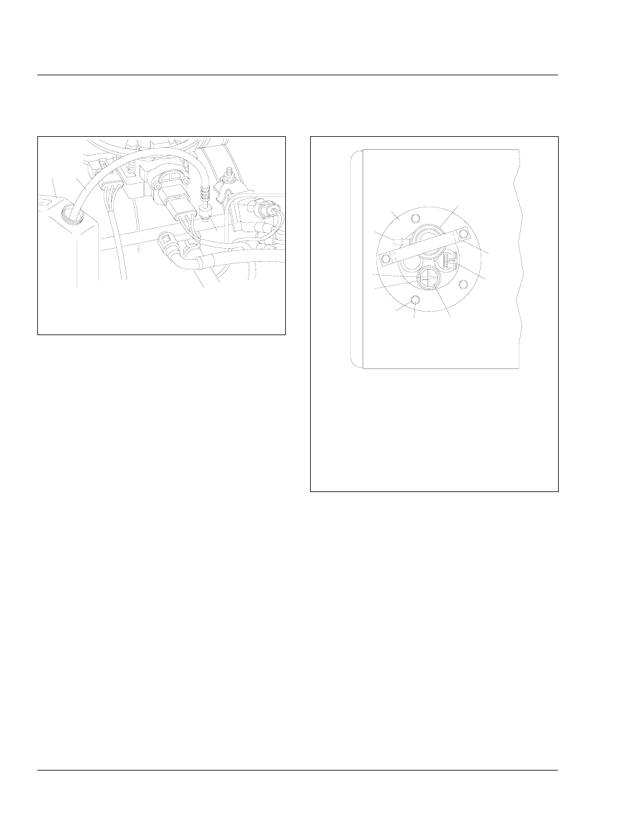
10. Position the fuel pump module in the orifice on
top of the fuel tank. Check that the fuel
filter/pressure regulator is facing the frame rail.
See
03/16/95
f010913
2
1
3
1.
Fuel Pressure Test Port
2.
Test Hose
3.
Approved Gasoline Can
Fig. 2, Relieving Fuel Pressure
03/17/95
f470135
4
5
6
7
8
9
10
1
2
3
1.
Fuel Filter/Pressure Regulator
2.
Fuel Pump Guard Bracket
3.
Fuel Pump/Gauge Electrical Connector
4.
Pressure Relief/Rollover Valve
5.
Clamp Ring Mounting Capscrew
6.
Hardened Flatwasher
7.
Rollover Valve Grommet
8.
EVAP Canister Connection
9.
Fuel Supply Line Connection
10. Fuel Pump Mounting Clamp Ring
Fig. 3, Fuel Pump Module (top view)
Fuel
47
Business Class Trucks Maintenance Manual, January 1998
47/2

11. Apply a light coat of silicone spray to the gasket
if needed to ease installation, then install the fuel
pump module in the fuel tank.
IMPORTANT: Only use grade 8 capscrews.
NOTE: Use the holes not intended for the
guard bracket.
11.1
Install the fuel pump clamp ring over the
fuel pump module, then install three
5/16–18 grade 8 capscrews and hard-
ened flatwashers to hold it in place. Do
not tighten the capscrews yet.
11.2
Install the fuel pump guard bracket over
the fuel filter/pressure regulator, then fas-
ten it in place with the remaining two cap-
screws and hardened flatwashers.
11.3
Tighten all five capscrews 15 lbf·ft (20
N·m).
12. Connect the fuel lines to the fittings on the fuel
filter/pressure regulator and the rollover valve.
Reconnect the electrical connector.
13. Fill the fuel tank with clean, unleaded gasoline.
14. Connect the batteries, start the engine, and
check for fuel leaks. Also check that the fuel
level gauge is working properly. Correct any fuel
leaks with the engine OFF.
03/03/95
f470136
1
2
3
4
5
4
6
6
7
1.
Fuel Level Float
2.
Fuel Gauge Sending Unit
3.
Electric Fuel Pump
4.
Retaining Tab
5.
In-Tank Fuel Filter
6.
Mounting Screw
7.
Electrical Wiring
Fig. 4, Fuel Pump Module (side view)
03/03/95
f470137
1
2
3
4
5
6
7
1.
Fuel Pump Module Gasket
2.
Fuel Pump Mounting Clamp Ring
3.
Fuel Pump Guard Bracket
4.
Clamp Ring Mounting Capscrew
5.
Hardened Flatwasher
6.
Fuel Tank
7.
Fuel Pump Module
Fig. 5, Fuel Pump Module (cutaway view)
Fuel
47
Business Class Trucks Maintenance Manual, January 1998
47/3
Title of Maintenance Operation (MOP)
MOP Number
Exhaust System Inspecting (Noise Emission Controls) . . . . . . . . . . . . . . . . . . . . . . . . . . . . . . . . . . . . . . . 49-01
Exhaust
49
Index, Alphabetical
Business Class Trucks Maintenance Manual, October 1998
49-01 Exhaust System
Inspecting (Noise
Emission Controls)
NOTE: In addition to the maintenance interval in
this manual, inspect the exhaust system if the
vehicle has a noticeable increase in noise level
at any time. Replace parts that show leakage,
wear, or damage.
1.
Check the muffler body, muffler outlet stack, muf-
fler shield, and inlet tubes, for leakage, dents,
corrosion, or holes in the muffler.
2.
Inspect the exhaust pipe for leakage, wear, or
damage; replace with new parts, if needed. Do
not reuse wide-band clamps. Once a clamp is
removed, it must be replaced.
2.1
On Caterpillar, Cummins, and Detroit Die-
sel engines, check for leakage at the
V-type clamp that attaches the exhaust
pipe to the turbocharger exhaust outlet. If
leakage exists, tighten the nut on the
V-type clamp 85 lbf·in (940 N·cm). If leak-
age persists, install a new V-band cou-
pling.
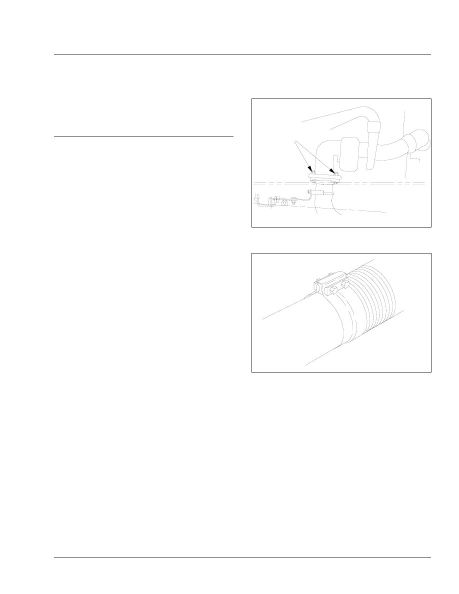
2.2
On Mercedes-Benz OM 366LA and
Dodge Magnum engines, check the tight-
ness of the fasteners that attach the ex-
haust pipe to the exhaust flange (
If needed, tighten the fasteners 33 lbf·ft
(45 N·m) for Mercedes-Benz OM 366LA
engines. For Dodge Magnum engines,
tighten the fasteners 25 lbf·ft (34 N·m).
3.
Check for leakage at each wide-band exhaust
clamp (
). If leakage exists, tighten the nuts
40 to 60 lbf·ft (54 to 81 N·m). If leakage persists,
install a new wide-band exhaust clamp. See
Group 49 of the
Business Class
®
Trucks Service
Manual
for procedures.
f490032a
10/05/94
A
A. Check the Tightness of These Fasteners
Fig. 1, Typical Exhaust-Pipe to Exhaust-Flange
Fasteners, OM 366 Engine Shown
f490005a
10/05/94
Fig. 2, Wide-Band Exhaust Clamp
Exhaust
49
Business Class Trucks Maintenance Manual, October 1998
49/1
Нет комментариевНе стесняйтесь поделиться с нами вашим ценным мнением.
Текст