Suzuki Grand Vitara JB627. Manual — part 325
8B-126 Air Bag System:
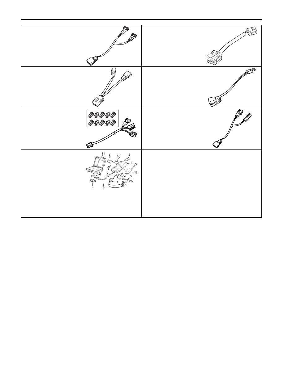
09932–76510
09932–77310
Deployment adapter cable
Deployment adapter cable
4P
09932–77320
09932–78310
Diagnosis adapter cable 4P
Adapter cable
09932–78332
09932–78340
Deployment adapter cable
Deployment adapter cable
SUZUKI scan tool
—
This kit includes following
items. 1. Tech 2, 2. PCMCIA
card, 3. DLC cable, 4. SAE
16/19 adapter, 5. Cigarette
cable, 6. DLC loop back
adapter, 7. Battery power
cable, 8. RS232 cable, 9.
RS232 adapter, 10. RS232
loop back connector, 11.
Storage case, 12. ) / )
Table of Contents 9- i
9
Section 9
CONTENTS
Body, Cab and Accessories
Precautions . . . . . . . . . . . . .9-1
Precautions. . . . . . . . . . . . . . . . 9-1
Wiring Systems. . . . . . . . . . 9A-1
Precautions. . . . . . . . . . . . . . ...9A-1
Cautions in Body Electrical System Servicing. . 9A-1
General Description . . . . . . . . . . . .9A-1
Abbreviations . . . . . . . . . . . . . .. 9A-1
Wire / Connector Color Symbols. . . . . . . 9A-1
Symbols and Marks . . . . . . . . . . . 9A-2
How to Read Connector Layout Diagram . . ... 9A-4
How to Read Connector Codes and Terminal
Nos. . . . . . . . . . . . . . . . . 9A-5
How to Read Ground Point . . . . . . . . . 9A-8
How to Read Power Supply Diagram. . . . .. 9A-9
How to Read System Circuit Diagram. . . ...9A-10
Connector Layout Diagram . . . . . . . ...9A-11
Connector Layout Diagram . . . . . . . ...9A-11
Engine Compartment . . . . . . . . . . 9A-12
Instrument Panel. . . . . . . . . . . ...9A-34
Door, Roof. . . . . . . . . . . . . . .9A-42
Floor. . . . . . . . . . . . . . . . .. 9A-46
Rear . . . . . . . . . . . . . . . . .. 9A-54
Ground Point . . . . . . . . . . . . . ..9A-55
Ground (earth) Point . . . . . . . . . . .9A-55
Power Supply Diagram . . . . . . . . . ..9A-57
Power Supply Diagram . . . . . . . . . . 9A-57
Fuses and the Protected Parts . . . . . . .9A-60
Fuses in Battery Fuse Box, Fuse Box No.1
(Petrol) . . . . . . . . . . . . . . . 9A-60
Fuses in Battery Fuse Box, Fuse Box No.1
(DSL). . . . . . . . . . . . . . . ... 9A-61
Fuse Box No.2 (In Power Integration No.1,
Power Integration No.2), Relay Box (Petrol)...9A-62
Fuse Box No.2 (In Power Integration No.1,
Power Integration No.2), Relay Box No.1,
Relay Box No.2 (DSL). . . . . . . . . . 9A-64
Fuse Box No.3 (In J/B). . . . . . . . . ..9A-66
Junction Block (J/B) Connector / Fuse Layout ..9A-68
Junction Block Inner Circuit (Overview) . . . 9A-68
Junction Block Inner Circuit (Detail) . . . . ..9A-70
System Circuit Diagram. . . . . . . . . .9A-74
System Circuit Diagram . . . . . . . . . 9A-74
A-1 Cranking System Circuit Diagram . . . ..9A-75
A-2 Charging System Circuit Diagram . . . ..9A-76
A-3 Ignition System Circuit Diagram (M16A) . 9A-77
A-3 Ignition System Circuit Diagram (J20A). ..9A-78
A-3 Ignition System Circuit Diagram (H27A). .9A-79
A-4 Cooling System Circuit Diagram (Petrol). 9A-81
A-4 Cooling System Circuit Diagram (DSL) . ..9A-82
A-5 Engine and A/C Control System Circuit
Diagram (M16A). . . . . . . . . . . ..9A-83
A-5 Engine and A/C Control System Circuit
Diagram (J20A) . . . . . . . . . . . ...9A-88
A-5 Engine and A/C Control System Circuit
Diagram (H27A) . . . . . . . . . . . ..9A-93
A-5 Engine and A/C Control System Circuit
Diagram (DSL) . . . . . . . . . . . . 9A-98
A-6 A/T Control System Circuit Diagram. . .9A-103
A-7 Immobilizer System Circuit Diagram . . 9A-106
A-8 Body Control System Circuit Diagram . ..9A-107
A-10 4WD Control System Circuit Diagram . 9A-112
B-1 Windshield Wiper and Washer Circuit
Diagram. . . . . . . . . . . . . . .9A-114
B-2 Rear Wiper and Washer Circuit Diagram .9A-115
B-3 Rear Defogger Circuit Diagram . . . . 9A-116
B-4 Power Window Circuit Diagram. . . . 9A-117
B-5 Power Door Lock Circuit Diagram . . . 9A-119
B-6 Power Mirror Circuit Diagram . . . . ...9A-121
B-7 Horn Circuit Diagram . . . . . . . . 9A-122
B-8 Seat Heater Circuit Diagram. . . . . .9A-123
B-9 Keyless Start System Circuit Diagram. ..9A-124
B-10 Sliding Roof Circuit Diagram . . . . ..9A-125
B-11 Headlight Cleaner Circuit Diagram . . .9A-126
C-1 Combination Meter Circuit Diagram . . .9A-127
D-1 Headlight System Circuit Diagram (One
bulb type) . . . . . . . . . . . . . ..9A-129
D-1 Headlight System Circuit Diagram (With
Projector light) . . . . . . . . . . . ...9A-130
D-1 Headlight System Circuit Diagram (With
Discharge bulb) . . . . . . . . . . . .9A-131
D-2 Position, Tail and Licence Plate Light
System Circuit Diagram . . . . . . . . 9A-132
D-3 Front Fog Light System Circuit Diagram ..9A-133
D-4 Illumination Light System Circuit Diagram 9A-134
D-5 Interior Light System Circuit Diagram. ...9A-135
9-ii Table of Contents
D-6 Turn Signal and Hazard Warning Light
System Circuit Diagram . . . . . . . . 9A-136
D-7 Brake Light System Circuit Diagram . . 9A-138
D-8 Back-Up Light System Circuit Diagram . 9A-139
D-9 Headlight Beam Leveling System Circuit
Diagram (Manual Leveling) . . . . . . ...9A-140
D-9 Headlight Beam Leveling System Circuit
Diagram (Auto Leveling) . . . . . . . ...9A-141
D-10 Rear Fog Light Circuit Diagram. . . ..9A-142
E-2 Auto A/C System Circuit Diagram . . . 9A-143
F-1 Air-Bag System Circuit Diagram (4ch). ..9A-145
F-1 Air-Bag System Circuit Diagram (8ch). ..9A-146
F-2 Anti-Lock Brake System Circuit Diagram..9A-148
F-3 Electronic Stability Program System
Circuit Diagram . . . . . . . . . . . .9A-150
G-1 Audio System Circuit Diagram . . . . .9A-152
G-2 Multi Information Display / Accessory
Socket System Circuit Diagram . . . . . 9A-154
G-4 Navigation System Circuit Diagram . . .9A-155
List of Connector . . . . . . . . . . . .9A-155
List of Connectors . . . . . . . . . . ...9A-155
B Connector . . . . . . . . . . . . . 9A-155
C Connector . . . . . . . . . . . . . 9A-156
D Connector . . . . . . . . . . . . . 9A-158
E Connector . . . . . . . . . . . . . 9A-159
F Connector . . . . . . . . . . . . . 9A-161
G Connector. . . . . . . . . . . . . 9A-162
J Connector. . . . . . . . . . . . . .9A-164
K Connector . . . . . . . . . . . . . 9A-166
L Connector. . . . . . . . . . . . . .9A-166
O Connector. . . . . . . . . . . . . 9A-168
Q Connector. . . . . . . . . . . . . 9A-169
R Connector . . . . . . . . . . . . . 9A-169
Lighting Systems . . . . . . . . . 9B-1
Precautions. . . . . . . . . . . . . . ...9B-1
Precautions for Discharge Headlight Service
(If Equipped) . . . . . . . . . . . . . .9B-1
Precautions in Diagnosing Troubles (Vehicle
Equipped with Auto Leveling Headlight
System) . . . . . . . . . . . . . . . .9B-1
General Description . . . . . . . . . . . .9B-2
Discharge Headlight Description (If
Equipped). . . . . . . . . . . . . . ..9B-2
Auto Leveling Headlight System Description
(If Equipped) . . . . . . . . . . . . . .9B-3
Auto-On Headlight System Description (If
Equipped). . . . . . . . . . . . . . ..9B-5
D.R.L. System Description (If Equipped) . . . 9B-6
Schematic and Routing Diagram. . . . . . 9B-6
Headlight Auto Leveling System Wiring
Circuit Diagram . . . . . . . . . . . . .9B-6
Component Location . . . . . . . . . . ...9B-7
Lighting System Components Location. . . ...9B-7
Interior Light System Location. . . . . . . .9B-8
Diagnostic Information and Procedures. . . 9B-8
Self-Diagnosis Function for Auto Leveling
Headlight System . . . . . . . . . . . ..9B-8
Headlight Leveling Warning Light Check . . . 9B-8
Headlight Symptom Diagnosis (Vehicle
Equipped with Discharge Headlight) . . . . .9B-9
Headlight Symptom Diagnosis (Vehicle Not
Equipped with Discharge Headlight) . . . . .9B-9
Auto-On Headlight System Symptom
Diagnosis (If Equipped). . . . . . . . ...9B-10
DRL System Symptom Diagnosis (If
Equipped). . . . . . . . . . . . . . 9B-10
Headlight Auto Leveling System Symptom
Diagnosis (If Equipped). . . . . . . . ...9B-11
Headlight Manual Leveling System Symptom
Diagnosis (If Equipped). . . . . . . . ...9B-11
Turn Signal and Hazard Warning Light
Symptom Diagnosis . . . . . . . . . . 9B-12
Clearance, Tail and License Plate Light
Symptom Diagnosis . . . . . . . . . . 9B-12
Equipped). . . . . . . . . . . . . . 9B-13
Rear Fog Light Symptom Diagnosis (If
Equipped). . . . . . . . . . . . . . 9B-13
Illumination Control System Symptom
Diagnosis (If Equipped). . . . . . . . ...9B-14
Interior Light Symptom Diagnosis . . . . . .9B-14
Auto-On Headlight Operation Inspection (If
Equipped). . . . . . . . . . . . . . 9B-14
DRL Operation Inspection (If Equipped) . . ...9B-15
Inspection of Headlight Leveling Control
Module and Its Circuit (Vehicle Equipped
with Auto Leveling Headlight System). . . .9B-15
Repair Instructions . . . . . . . . . . . 9B-17
Headlight Housing Removal and Installation . 9B-17
Headlight Bulb Replacement. . . . . . . .9B-17
Ballast Removal and Installation . . . . . ...9B-19
Igniter Removal and Installation. . . . . . 9B-19
Headlight Aiming Adjustment with Screen . . 9B-20
Headlight Switch (in Lighting Switch)
Removal and Installation. . . . . . . . .9B-22
Headlight Switch (in Lighting Switch)
Inspection. . . . . . . . . . . . . . 9B-22
Tail Light Relay, Headlight Relay Inspection. .9B-23
Hazard Warning Switch Removal and
Installation . . . . . . . . . . . . . ...9B-23
Hazard Warning Switch Inspection . . . . ...9B-23
Brake Light Switch Inspection . . . . . . ...9B-23
Turn Signal Light Switch (in Lighting Switch)
Removal and Installation. . . . . . . . .9B-24
Turn Signal Light Switch (in Lighting Switch)
Inspection. . . . . . . . . . . . . . 9B-24
Turn Signal and Hazard Warning Relay
Removal and Installation. . . . . . . . .9B-24
Turn Signal and Hazard Warning Relay
Inspection. . . . . . . . . . . . . . 9B-24
License Light Assembly Removal and
Installation . . . . . . . . . . . . . ...9B-25
Front Fog Light Assembly Removal and
Installation (If Equipped) . . . . . . . . .9B-25
Table of Contents 9-iii
Front Fog Light Switch Inspection (If
Equipped). . . . . . . . . . . . . . 9B-25
Front Fog Light Relay Inspection (If
Equipped). . . . . . . . . . . . . . 9B-26
Front Fog Light Aiming Adjustment with
Screen (If Equipped) . . . . . . . . . ... 9B-27
Headlight Manual Leveling Switch (If
Equipped) Inspection . . . . . . . . . ..9B-28
Headlight Leveling Actuator Inspection (If
Equipped). . . . . . . . . . . . . . 9B-28
Rear Fog Light Switch Inspection (If
Equipped). . . . . . . . . . . . . . 9B-29
Height Sensor Removal and Installation (If
Equipped). . . . . . . . . . . . . . 9B-29
Height Sensor and Its Circuit Inspection (If
Equipped). . . . . . . . . . . . . . 9B-30
Leveling Control Module Removal and
Installation (If Equipped) . . . . . . . . . 9B-31
Initialization of Auto Leveling Headlight
System . . . . . . . . . . . . . . . 9B-31
Auto-On Headlight Sensor Inspection (If
Equipped). . . . . . . . . . . . . . 9B-32
Specifications. . . . . . . . . . . . . .9B-32
Tightening Torque Specifications. . . . . ..9B-32
Instrumentation / Driver Info. / Horn . .. 9C-1
Precautions. . . . . . . . . . . . . . ...9C-1
Precautions in Diagnosing Troubles for
Combination Meter. . . . . . . . . . . 9C-1
General Description . . . . . . . . . . . .9C-1
CAN Communication System Description. . ...9C-1
Auto Volume Control System Description (If
Equipped). . . . . . . . . . . . . . ..9C-3
Schematic and Routing Diagram. . . . . . 9C-4
Combination Meter Circuit Diagram . . . . . 9C-4
Component Location . . . . . . . . . . ...9C-5
Audio System Component Location. . . . . 9C-5
Diagnostic Information and Procedures. . . 9C-6
Symptom Diagnosis . . . . . . . . . . ..9C-6
Fuel Meter Symptom Diagnosis. . . . . . ..9C-6
Low Fuel Warning Light Symptom Diagnosis . .9C-7
Oil Pressure Warning Light Symptom
Diagnosis . . . . . . . . . . . . . . ..9C-7
Brake and Parking Brake Warning Light
Symptom Diagnosis . . . . . . . . . . ..9C-8
Seat Belt Reminder Light Symptom Diagnosis
(If Equipped) . . . . . . . . . . . . . .9C-8
Illumination Indicator Symptom Diagnosis . . ..9C-9
Headlight Auto Leveling Indicator Symptom
Diagnosis (If Equipped). . . . . . . . . .9C-9
A/T Power Mode Indicator Symptom
Diagnosis (A/T Model) . . . . . . . . . 9C-10
A/T Shift Position Indicator Symptom
Diagnosis (A/T Model) . . . . . . . . . 9C-10
Charge Warning Light Symptom Diagnosis . ..9C-10
Main Beam (High Beam) Indicator Symptom
Diagnosis . . . . . . . . . . . . . . 9C-11
Warning Buzzer Circuit Symptom Diagnosis . 9C-11
Cigarette Lighter Symptom Diagnosis (If
Equipped). . . . . . . . . . . . . . 9C-12
Horn Symptom Diagnosis . . . . . . . . .9C-12
Information Display Symptom Diagnosis (If
Equipped). . . . . . . . . . . . . . 9C-12
Clock Symptom Diagnosis (If Equipped). . ...9C-13
Audio System Symptom Diagnosis (If
Equipped). . . . . . . . . . . . . . 9C-14
Remote Audio Control Switch Symptom
Diagnosis (If Equipped). . . . . . . . ...9C-15
Navigation Symptom Diagnosis (If Equipped)...9C-15
Repair Instructions . . . . . . . . . . . 9C-16
Ignition Switch Removal and Installation. . ...9C-16
Ignition Switch Inspection. . . . . . . . ..9C-16
Combination Meter Removal and Installation ...9C-17
Fuel Level Sensor Removal and Installation. .9C-17
Fuel Level Sensor Inspection. . . . . . . 9C-17
Oil Pressure Switch Removal and Installation ..9C-18
Oil Pressure Switch Inspection . . . . . . .9C-18
Engine Coolant Temperature (ECT) Sensor
Inspection. . . . . . . . . . . . . . 9C-18
Brake Fluid Level Switch Inspection . . . . .9C-18
Parking Brake Switch Inspection. . . . . ...9C-18
Door Switch (Front / Rear / Rear End Door)
Inspection. . . . . . . . . . . . . . 9C-19
Outside Air Temperature Sensor Removal
and Installation (If Equipped) . . . . . . ..9C-19
Outside Air Temperature Sensor Inspection
(If Equipped). . . . . . . . . . . . . 9C-19
Instrument Panel Removal and Installation. ...9C-20
Information Display (Clock) Removal and
Installation . . . . . . . . . . . . . ...9C-21
Audio Unit Removal and Installation . . . . .9C-21
Front Speaker Removal and Installation . . ...9C-22
Rear Speaker Removal and Installation (5
Door Model) . . . . . . . . . . . . . 9C-22
Rear Speaker Removal and Installation (3
Door Model) . . . . . . . . . . . . . 9C-22
GPS Antenna Removal and Installation (If
Equipped). . . . . . . . . . . . . . 9C-23
Horn Removal and Installation . . . . . . ..9C-23
Horn Inspection . . . . . . . . . . . . .9C-23
Horn Relay Inspection. . . . . . . . . ...9C-24
Antenna Base Removal and Installation . . ...9C-24
Remote Audio Control Switch Removal and
Installation (If Equipped) . . . . . . . . .9C-25
Remote Audio Control Switch Inspection (If
Equipped). . . . . . . . . . . . . . 9C-25
Vehicle Speed Signal Inspection (For Audio
Unit) (If Equipped) . . . . . . . . . . ...9C-25
Specifications. . . . . . . . . . . . . .9C-26
Tightening Torque Specifications. . . . . ..9C-26
Wipers / Washers. . . . . . . . . . 9D-1
Diagnostic Information and Procedures. . . 9D-1
Front Wiper and Washer Symptom Diagnosis . 9D-1
Rear Wiper and Washer Symptom Diagnosis. .9D-1
Нет комментариевНе стесняйтесь поделиться с нами вашим ценным мнением.
Текст