Suzuki Grand Vitara JB627. Manual — part 320
8B-106 Air Bag System:
Installation
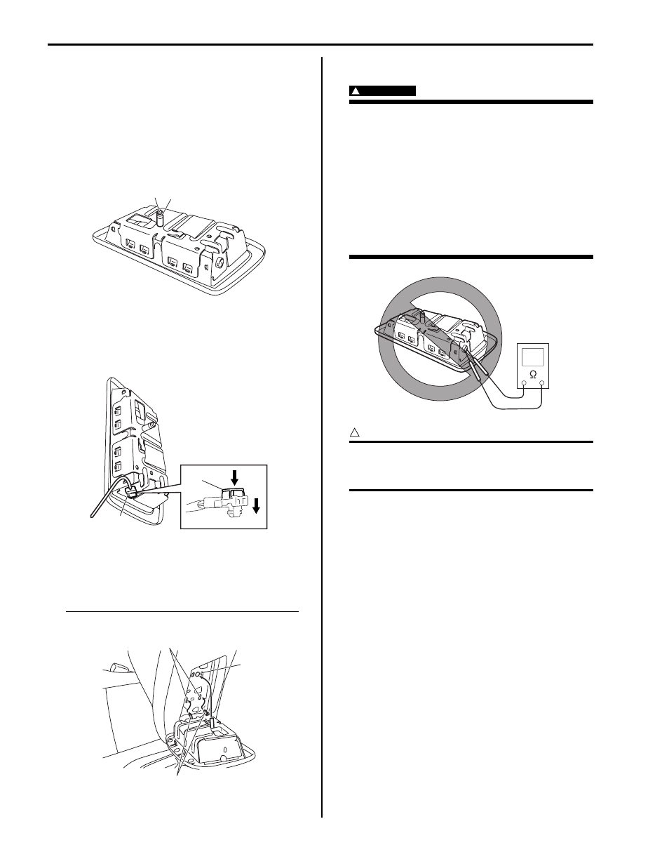
1) Confirm sleeve (1) is surely installed in side-air bag
(inflator) module.
2) Tighten sleeve lock nut (2) to specified torque.
Tightening torque
Sleeve lock nut (a): 2.5 N·m (0.25 kgf-m, 2.0 lb-
ft)
3) Install new clip to seat back.
4) Connect side-air bag (inflator) module connector (1)
securely as shown in figure.
a) Connect connector.
b) Lock connector with lock button (2).
5) Insert claw (1) of side-air bag (inflator) module on
installation hole (2).
6) Push side-air bag (inflator) module into clip (3) with
specified force.
Side-air bag (inflator) module installation force
Pushing force: 180 N
Side-Air Bag (Inflator) Inspection
S6JB0B8206010
WARNING
!
• Never attempt to disassemble or repair the
side-air bag (inflator) module. If any
abnormality is found, be sure to replace it
with new one as an assembly.
• Be sure to read “Precautions on Service
and Diagnosis of Air Bag System” before
starting to work and observe every
precaution during work. Neglecting them
may result in personal injury or
undeployment of the air bag when
necessary.
CAUTION
!
If air bag (inflator) module was dropped from
a height of 90 cm (3 ft) or more, it should be
replaced.
Check air bag (inflator) module appearance visually for
the following symptoms and if any one of them is found,
replace with a new one.
• Air bag has deployed.
• There is a crack in trim cover (pad surface).
• Wire harness or connector is damaged.
• Air bag (inflator) module is damaged or a strong
impact was applied to it.
• Bend or deformity of air bag (inflator) module bracket.
1
2, (a)
I4RS0A820073-02
1
2
a)
b)
I4RS0A820070-01
1
2
3
I4RS0A820074-02
I4RS0A820075-02
Air Bag System: 8B-107
Side Curtain-Air Bag (Inflator) Module Removal
and Installation
S6JB0B8206011
WARNING
!
• Never attempt to disassemble or repair the
side curtain-air bag (inflator) module. If any
abnormality is found, be sure to replace it
with new one as an assembly.
• Be sure to read “Precautions on Service
and Diagnosis of Air Bag System”,
“Precautions on Handling and Storage of
Air Bag System Components” and
“Precautions on Disposal of Air Bag and
Seat Belt Pretensioner” before starting to
work and observe every precaution during
work. Neglecting them may result in
personal injury or undeployment of the air
bag when necessary.
Removal
1) Disable air bag system. Refer to “Disabling Air Bag
2) Remove head lining referring to “Head Lining
Removal and Installation in Section 9H”.
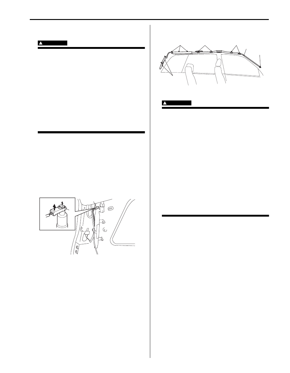
3) Disconnect side curtain-air bag (inflator) module
connector (1) as shown in figure.
a) Unlock lock button (2).
b) With lock button unlocked, disconnect connector.
4) Remove side curtain-air bag (inflator) module bolts
(1) and clip (2).
5) Remove side curtain-air bag (inflator) module.
WARNING
!
• When carrying a live air bag (inflator)
module, make sure the bag opening is
pointed away from you.
Never carry air bag (inflator) module by
wires or connector on the side of the
module. In case of an accidental
deployment, the bag will then deploy with
minimal chance of injury.
• As the live curtain air bag (inflator) module
must be kept with its bag facing up while
being stored or left standing. This is
necessary so that a free space is provided
to allow the air bag to expand in the
unlikely event of accidental deployment.
• Observe “Precautions on Handling and
Storage of Air Bag System Components”
for handling and storing it.
Otherwise, personal injury may result.
b)
a)
2
1
I5JB0A820085-01
1
2
1
1
1
1
I5JB0A820086-01
8B-108 Air Bag System:
Installation
WARNING
!
Do not install side curtain-air bag (inflator)
module while twisted or bent. Otherwise, side
curtain-air bag (inflator) module may not
deploy and injury may result.
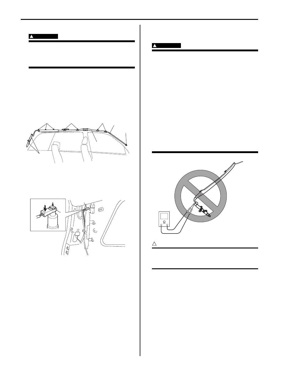
1) Install side curtain-air bag (inflator) module (1) with
clip (2) and bolts.
2) Tighten side curtain-air bag (inflator) module bolts (3)
to specified torque.
Tightening torque
Side curtain-air bag (inflator) module bolts (a):
10 N·m (1.0 kgf-m, 7.5 lb-ft)
3) Connect side curtain-air bag (inflator) module
connector (1) securely as shown in figure.
a) Connect connector.
b) Lock connector with lock button (2).
4) Install head lining referring to “Head Lining Removal
and Installation in Section 9H”.
5) Enable air bag system. Refer to “Enabling Air Bag
Side Curtain-Air Bag (Inflator) Module
Inspection
S6JB0B8206012
WARNING
!
• Never measure resistance of side curtain-
air bag (inflator) module or disassemble it.
Otherwise personal injury may result.
• Never attempt to disassemble or repair the
side curtain-air bag (inflator) module. If any
abnormality is found, be sure to replace it
with new one as an assembly.
• Be sure to read “Precautions on Service
and Diagnosis of Air Bag System”,
“Precautions on Handling and Storage of
Air Bag System Components” and
“Precautions on Disposal of Air Bag and
Seat Belt Pretensioner” before starting to
work and observe every precaution during
work. Neglecting them may result in
personal injury or undeployment of the air
bag when necessary.
CAUTION
!
If air bag (inflator) module was dropped from
a height of 90 cm (3 ft) or more, it should be
replaced.
Check air bag (inflator) module appearance visually for
the following symptoms and if any one of them is found,
replace with a new one.
• Air bag has deployed.
• Inflator case being damaged or having been exposed
to strong impact (dropped).
3, (a)
3, (a)
3, (a)
3, (a)
3, (a)
1
2
I5JB0A820087-01
2
b)
a)
1
I5JB0A820088-01
I5JB0A820089-02
Air Bag System: 8B-109
Forward-Sensor Removal and Installation
S6JB0B8206013
WARNING
!
During service procedures, be very careful
when handling a sensor.
• Never strike or jar a sensor.
• A sensor and mounting bracket bolts must
be carefully torqued to assure proper
operation. Under loose connection, it
could cause improper operation of the air
bag system.
Removal
1) Disconnect negative cable at battery.
2) Disable air bag system referring to “Disabling Air
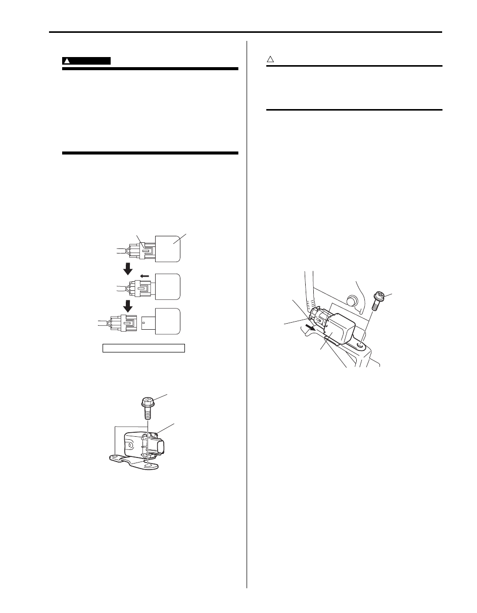
3) Disconnect forward-sensor connector sliding
connector outer (2) as shown.
4) Remove forward-sensor bolts (1) and forward-
sensor (2).
Installation
CAUTION
!
Proper operation of forward-sensor requires
sensor be rigidly attached to vehicle
structure and that the arrow on sensor be
pointing toward the front of the vehicle.
1) Check that none of the following faulty conditions
exists.
• Bend, deformity or rust of front panel.
• Foreign matter on mating surface of sensor.
2) Apply thread lock cement to mounting bolts thread.
Install forward-sensor (1) on bracket and tighten
mounting bolt (2) to specified torque.
“A”: Thread lock cement 99000–32100 (Thread
Lock Cement 1305)
Tightening torque
Forward-sensor mounting bolt (a): 11 N·m (1.1
kgf-m, 8.0 lb-ft)
3) Connect forward-sensor connector (3) by pushing
connector till click is heard from it.
4) Connect negative cable at battery.
5) Enable air bag system referring to “Enabling Air Bag
1. Forward sensor
2
1
I5JB0A820090-01
1
2
I5JB0A820091-03
1
3
2, “A”, (a)
I5JB0A820092-01
Нет комментариевНе стесняйтесь поделиться с нами вашим ценным мнением.
Текст