Suzuki Grand Vitara JB627. Manual — part 226

5A-88 Automatic Transmission/Transaxle:
Manual Selector Assembly Components
S6JB0B5106005
Manual Selector Assembly Removal and
Installation
S6JB0B5106006
Removal
1) Disconnect negative cable at battery.
2) Remove front center console box.
3) Disconnect shift lever switch connector.
4) Remove manual selector assembly mounting bolts.
5) Disconnect select cable (1) from manual selector
assembly (2) expanding select cable clip (3).
Installation
Reverse removal procedure to install manual selector
assembly noting the following instructions.
• Tighten manual selector assembly mounting bolts to
specified torque.
Tightening torque
Manual selector assembly mounting bolt: 18 N·m
(1.8 kgf-m, 13.0 lb-ft)
Select Lever Knob Installation
S6JB0B5106007
Screw select lever knob onto select lever by specified
numbers of rotation below.
Rotation numbers for select lever knob
Installation (a): 13 – 14 rotations
CAUTION
!
When installing select lever knob, do not turn
more than specified numbers of rotation.
Otherwise select lever knob is damaged.
Manual Selector Assembly Inspection
S6JB0B5106008
Check select lever for smooth and clear-cut movement
individually and position indicator for correct indication.
If a malfunction is found, replace select lever assembly.
1. Manual lever assembly
2. Select indicator assembly
3. Illumination light assembly
4. Knob
5. Manual selector assembly mounting bolt
6. Slide cover
: 1.8 N
⋅m (1.8 kgf-m, 13.0 lb-ft.)
4
2
6
1
5
(a)
3
I5JB0A510033-01
1
2
I5JB0A510034-02
1
2
I5JB0A510034-02
1,(a)
I4RS0A510058-01
Automatic Transmission/Transaxle: 5A-89
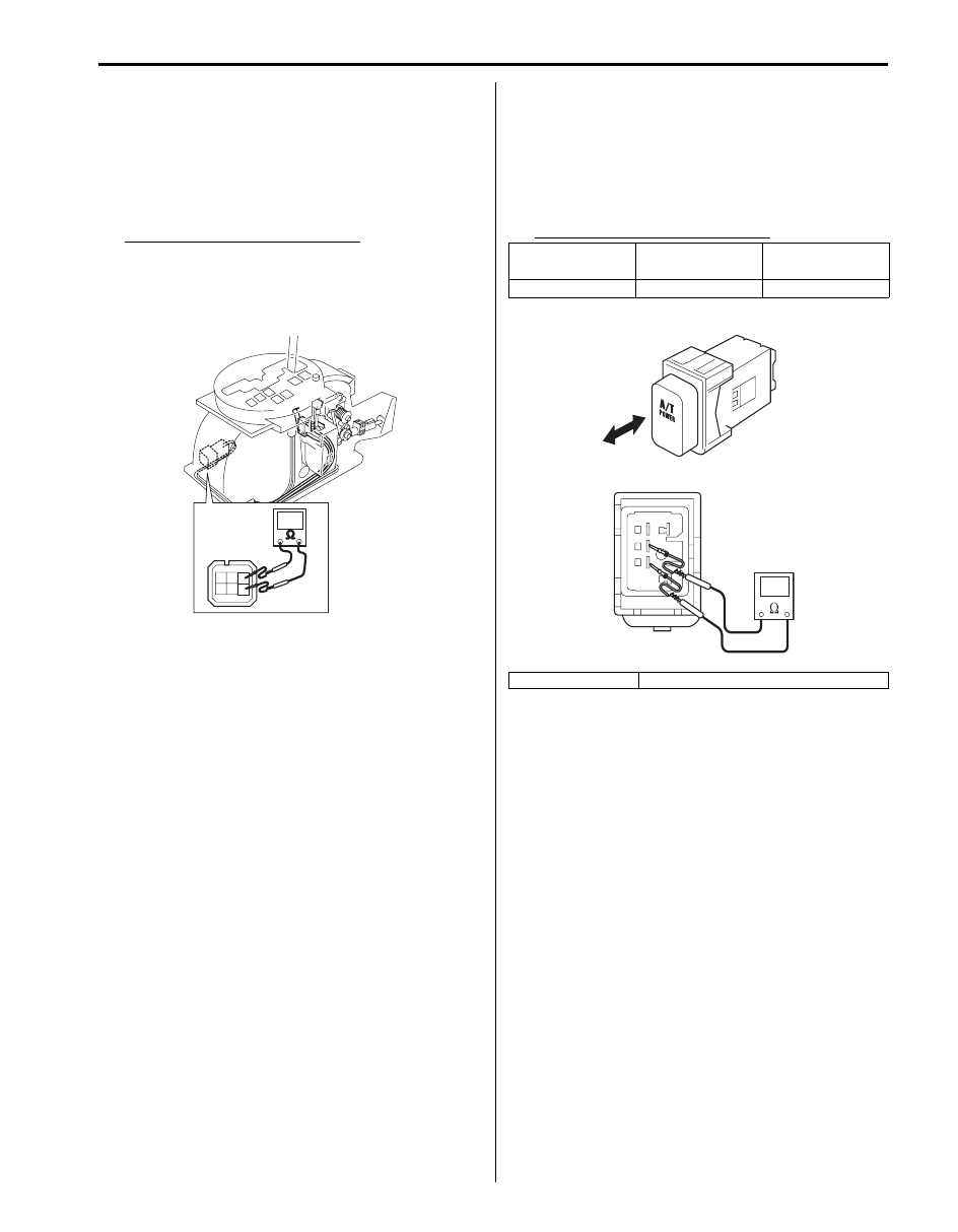
“4” Position Switch Inspection
S6JB0B5106009
1) Disconnect negative cable at battery.
2) Remove front console box.
3) Disconnect manual selector connector (1).
4) Measure resistance between “4” position switch
terminals.
“4” position switch specification
Shift selector lever to “P”, “N” or “D” range: 3.96
– 4.04 k
Ω
Shift selector lever to “R”, “4”, “3” or “L” range:
0.99 – 1.01 k
Ω
Mode Select Switch Inspection
S6JB0B5106010
1) Pull out mode select switch from front center console
box.
2) Disconnect mode select switch connector.
3) Check continuity between mode select switch
terminals.
Mode select switch specification
I5JB0A510164-01
Mode select
switch
Normal position Power position
Continuity
No continuity
Continuity
A: Push
B: Push again to release
B
A
I5JB0A510042-01
5A-90 Automatic Transmission/Transaxle:
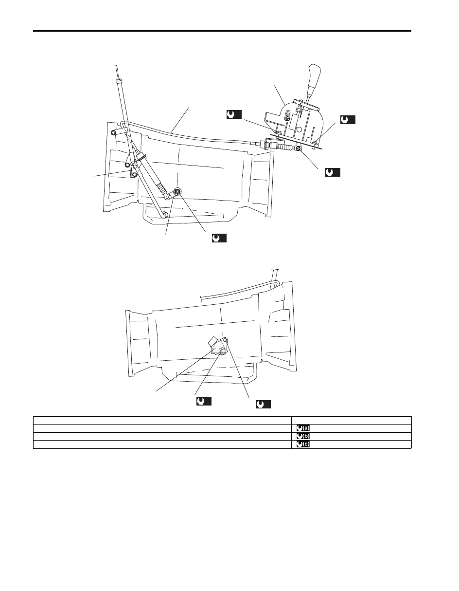
Select Cable Component
S6JB0B5106011
(a)
7
(b)
6
(a)
2
1
(a)
2
3
4
8
(b)
9
(a)
7
5
I6JB01510019-01
1. Manual selector assembly
5. Manual select lever
9. Transmission range sensor bolt
2. Manual selector assembly mounting bolt
6. Manual select cable end nut
: 18 N
⋅m (1.8 kgf-m, 13.0 lb-ft.)
3. Select cable
7. Manual select lever nut
: 13 N
⋅m (1.3 kgf-m, 9.5 lb-ft.)
4. Select cable bracket
8. Transmission range sensor
: 12.5 N
⋅m (1.25 kgf-m, 9.0 lb-ft.)
Automatic Transmission/Transaxle: 5A-91
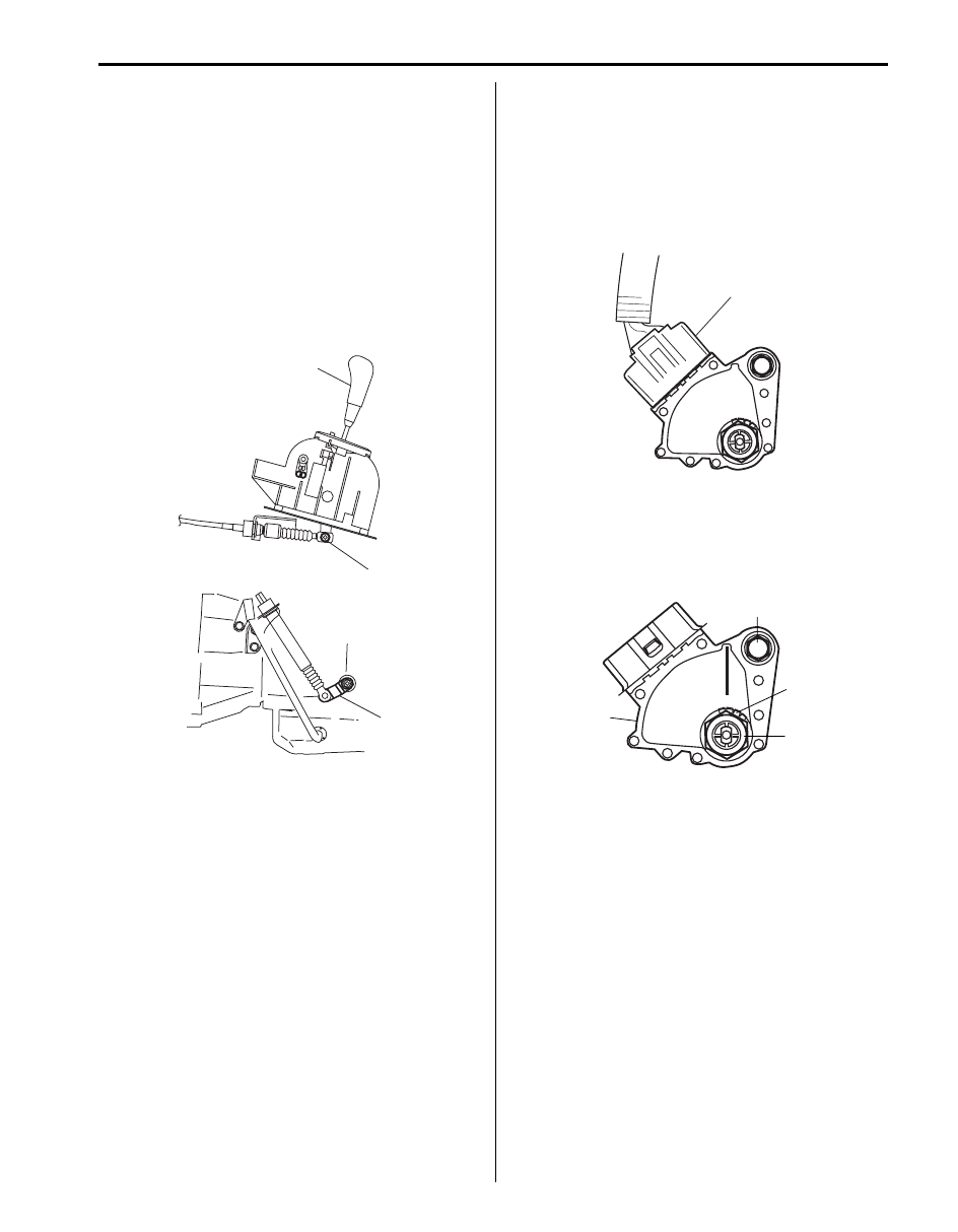
Select Cable Adjustment
S6JB0B5106012
1) Remove manual selector, refer to “Manual Selector
Assembly Removal and Installation” with select
cable connected.
2) Loosen manual select cable end nut (1).
3) Shift select lever (2) and manual select lever (3) to
“N”.
4) Tighten manual select cable end nut (1) to specified
torque.
Tightening torque
Manual select cable end nut (a): 13 N·m (1.3 kgf-
m, 9.5 lb-ft)
5) After select cable was installed, check for the
following.
• Push vehicle with selector lever shifted to “P”.
Vehicle should not move.
• Vehicle can not be driven in “N”.
• Vehicle can be driven in “D”, “4” and “L”.
• Vehicle can be backed in “R”.
Transmission Range Sensor Removal and
Installation
S6JB0B5106013
Removal
1) Disconnect negative cable at battery.
2) Hoist vehicle.
3) Disconnect transmission range sensor connector
(1).
4) Unbend bend parts of lock washer (1), then remove
manual shift shaft nut (2), lock washer (1) and
grommet.
5) Remove transmission range sensor (3) by removing
sensor bolt (4).
2
3
1, (a)
I6JB01510020-01
1
I6JB01510021-01
4
3
1
2
I4JA01512011-01
Нет комментариевНе стесняйтесь поделиться с нами вашим ценным мнением.
Текст