Suzuki Grand Vitara JB627. Manual — part 293

8A-5 Seat Belts:
Front Seat Belt Inspection
S6JB0B8106003
WARNING
!
• Never attempt to disassemble or repair the
seat belt pretensioner (retractor
assembly). If any abnormality is found, be
sure to replace it with new one as an
assembly.
• Be sure to read “Precautions on Service
and Diagnosis of Seat Belt”, before
starting to work and observe every
precaution during work. Neglecting them
may result in personal injury or
unactivation of the seat belt pretensioner
when necessary.
• Never measure resistance of pretensioner
or disassemble it. Otherwise, personal
injury may result.
CAUTION
!
If seat belt pretensioner (retractor assembly)
was dropped from a height of 30 cm (1 ft) or
more, it should be replaced.
Seat belts and attaching parts can affect the vital
components and systems of a vehicle.
Therefore, they should be inspected carefully and
replaced with genuine parts only.
Seat Belt
• The seat belt webbing or strap should be free from
damage.
Retractor Assembly (with Seat Belt Pretensioner)
1) Let the seat belt retract fully to confirm its easy
retraction.
• The retractor assembly should lock webbing when
pulled quickly.
• The front seat belt retractor assembly (1) should
pass the inspection and should lock webbing even
when tilted (approx. 15
°) toward the fore and aft or
right and left directions.
2) Check retractor assembly (1) with seat belt
pretensioner appearance visually for following
symptoms and if any one of them is applicable,
replace it with a new one as an assembly.
• Pretensioner has activated.
• There is a crack in seat belt pretensioner
(retractor assembly).
• Seat belt pretensioner (retractor assembly) is
damaged or a strong impact (e.g., dropping) was
applied to it.
Anchor Bolt
• Anchor bolts should be torqued to specification.
Belt Latch
• It should be secure when latched.
Seat Belt Switch
Check driver side seat belt switch for continuity by using
ohmmeter.
Seat belt switch specification
Without inserted buckle tongue to buckle catch:
Terminal “A” and “B”: Continuity
With inserted buckle tongue to buckle catch:
Terminal “A” and “B”: No continuity
I5JB0A810005-02
1. Buckle tongue
2. Buckle catch
I2RH01810005-01
I4RS0B810001-01
Seat Belts: 8A-6
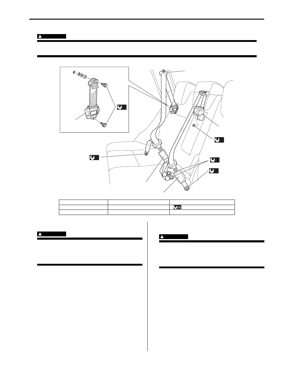
Rear Seat Belt Components
S6JB0B8106004
WARNING
!
Be sure to read “Precautions on Service and Diagnosis of Seat Belt” before starting to work and
observe every precaution during work.
Rear Seat Belt Removal and Installation
S6JB0B8106005
WARNING
!
Be sure to read “Precautions on Service and
Diagnosis of Seat Belt” before starting to
work and observe every precaution during
work.
Removal
1) Remove rear side sill scuff, rear side lower trim and
rear pillar trim referring to “Head Lining Removal and
Installation in Section 9H”.
2) Remove rear seat belt referring to “Rear Seat Belt
Installation
Reverse removal procedure for installation noting the
following.
• Seat belt anchor bolts should have an unified fine
thread (7/16-20 UNF). Under no circumstances
should any different sized or metric screw threads be
used.
Rear Seat Belt Inspection
S6JB0B8106006
WARNING
!
Be sure to read “Precautions on Service and
Diagnosis of Seat Belt” before starting to
work and observe every precaution during
work.
• Check the rear seat belt in the same way as “Front
• As to seat belts with A-ELR, check them as follows.
– With vehicle at stop, pull seat belt all the way out,
let it retract a little and try to pull it. It should not be
pulled out, that is, it should be locked where
retracted.
– Let seat belt retract to its original state. Next, pull it
half way out, let it retract a little and try to pull it
again. It should be pulled out smoothly, that is it
should not be locked at this time.
(a)
(a)
(a)
(a)
(a)
3
1
4
6
5
2
I5JB0A810006-01
1. Upper anchor
4. Rear center retractor assembly
7. Rear seat belt
2. Lower anchor
5. Buckle for rear seat belt
: 35 N
⋅m (3.5 kgf-m, 25.5 lb-ft)
3. Retractor assembly
6. Buckle for rear center seat belt
8A-7 Seat Belts:
Specifications
Tightening Torque Specifications
S6JB0B8107001
NOTE
The specified tightening torque is also described in the following.
“Front Seat Belt Components”
“Rear Seat Belt Components”
Reference:
For the tightening torque of fastener not specified in this section, refer to “Fastener Information in Section 0A”.

Air Bag System: 8B-1
Restraint
Air Bag System
Precautions
Precautions on Service and Diagnosis of Air
Bag System
S6JB0B8200001
WARNING
!
• If the air bag system and another vehicle
system both need repair, SUZUKI
recommends that the air bag system be
repaired first, to help avoid unintended air
bag system activation.
• Do not modify the steering wheel,
dashboard, both front seat or any other on
or around air bag system components.
Modifications can adversely affect air bag
system performance and lead to injury.
• Be sure to follow the procedures described
in this section. Failure to follow
procedures could result in possible air bag
system activation, personal injury or
unneeded air bag system repairs.
• WARNING / CAUTION labels are attached on each
part of air bag system components (SDM, air bag
(inflator) modules and seat belt pretensioners). Be
sure to follow the instructions.
• Many of service procedures require disconnection of
“A/B” fuse and air bag (inflator) module(s) (driver,
passenger, side of both sides and curtain of both
sides) from initiator circuit to avoid an accidental
deployment.
• Do not apply power to the air bag system unless all
components are connected or a diagnostic flow
requests it, as this will set a DTC.
• The “Air Bag Diagnostic System Check” must be the
starting point of any air bag diagnostics. The “Air Bag
Diagnostic System Check” will verify proper “AIR
BAG” warning light operation and will lead you to the
correct flow to diagnose any air bag malfunctions.
Bypassing these procedures may result in extended
diagnostic time, incorrect diagnosis, and incorrect
parts replacements.
• Never use air bag component parts from another
vehicle.
• If the vehicle will be exposed to temperatures over 93
°C (200 °F) (for example, during a paint baking
process), remove the air bag system components
beforehand to avoid component damage or
unintended system activation.
• When handling the air bag (inflator) modules (driver,
passenger, side of both sides and curtain of both
sides), seat belt pretensioners (driver and passenger),
SDM, forward-sensor or side-sensor, be careful not to
drop it or apply an impact to it. If an excessive impact
was applied (e.g., SDM, forward-sensor and side-
sensor are dropped, air bag (inflator) module is
dropped from a height of 90 cm (3 ft) or more, seat
belt pretensioner (retractor assembly) is dropped from
a height of 30 cm (1 ft) or more), never attempt
disassembly or repair but replace it with a new one.
• When using electric welding, be sure to disconnect air
bag (inflator) module connectors (driver, passenger,
side of both sides and curtain of both sides) and seat
belt pretensioner connectors (driver and passenger)
respectively.
• When applying paint around the air bag system
related parts, use care so that the harness or
connector will not be exposed to the paint mist.
• Never expose air bag system component parts
directly to hot air (drying or baking the vehicle after
painting) or flames.
WARNING
!
When performing service on or around air
bag system components or air bag wiring,
follow the procedures listed in “Disabling Air
Bag System” to temporarily disable the air
bag system.
Failure to follow procedures could result in
possible air bag system activation, personal
injury or unneeded air bag system repairs.
Нет комментариевНе стесняйтесь поделиться с нами вашим ценным мнением.
Текст